Quantcast
Channel: The Carpentry Way
Viewing all 533 articles
Browse latest View live

A Square Deal (4)

$
0
0
This is a series of posts describing the design and build of a coffee table and possibly more. Click here for Post 1, with subsequent posts links to be found at the bottom of each entry.

In the previous post, I mentioned that the hunt for suitable material with which to construct the coffee table had widened from the initial consideration of Claro Walnut to include other woods, notably bubinga. I had found a large piece of 12/4 bubinga, 16' long and 50" wide, and suggested to the client that it would likely be the best choice for this project, especially given the possibility that I would be designing and building a sideboard as well, which could be constructed out of the same slab of wood.

The ball was in the client's court, and he checked in with me to ascertain whether I felt I had exhausted the options I had been looking at, to which I replied I had. Of course, given an extended period of time to continue hunting, who knows what sort of material might come to light, however I also tend to think that when you come across the right thing - -well, it's a bird in the hand instead of two in the bush sort of situation. I think the likely future supply of thick and wide bubinga slabs looks uncertain at best, so, carpe lignum. (I'm just making that Latin up, and hopefully nobody will be too cross about it)

The client got back to me the next day, and, having thought it over, decided he would buy the bubinga slab! The first thing that came to me was a feeling of delight and excitement. The second thing to come to me was a feeling of mild apprehension, as I was wondering exactly how I would get this behemoth of a board into my shop. Besides the fact that there is no forklift at my shop space, the board is too wide to go through the freight door, unless it is on edge, and I was frankly on edge myself thinking about trying to maneuver something like that on its edge. I probably won't be doing it that way. It will have to come through the double front doors, just like the deliveries of machinery I've have over the past year. I think I've figured the logistics out and should be able to manage once the board gets here. It will involve a tow truck, and hopefully no one will get flattened or throw their back out.

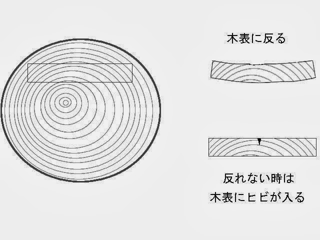
I also have some anticipatory apprehension in regards to the thought of cutting into this mega slab of wood. I always think of a line in Krenov's The Fine art of Cabinetmaking, where there's a picture of a slab of wood and a handsaw a good way into a cross cut - the caption reads:

Cross-cutting should always be preceded by careful thought

How true that is. Careful thought, if not mild terror. He also noted,

Even with years of experience, one must concentrate when sawing the wood to size, since between hope and result there lies a line called attention.

----------

I've been fine-tuning the design, and thought I would share some pictures of how things currently stand.

First, a perspective view:


A plan view of the table top:


I've changed the length of the mitered abutments between bread board ends and table top to better accommodate the connection between the top of the table frame.

Elevation view:


After trying various forms for the pillow blocks, I decided to make them overtly architectural, proportioning them using one Japanese method, the 'division by 5.5 pattern' (one of several used in Japanese architecture), and then elongating the blocks. Normally they would be square of course.

A bit of what is going on joinery-wise at one of the corners:


In the view shown above, there are some details yet to be added.

One difference between the current piece and the earlier version shown a couple of posts back is that the lead edge of the legs, along with the upper outer arris of the rails and the lower arris of the table top all have concave bead molding, whereas previously they were flat chamfered. Flat chamfers remain on the table's upper arris, on the side arrises of the legs and on the stretchers.

After extensive study, I've also come up with a slightly different way (at least, in light of what I have seen before) of doing the 3-way mitered connections between leg and rails, and will talk more about that in a later post. If you're interested in the topic of Chinese 3-way miter joints, I did talk a bit about that in a post from a few years back. Click here to read more.

In recent emails with the client he ran by me the idea of adding a drawer or drawers, to the table,  and asked me what I thought of that. While I could see different ways in which it could be done, after mulling it over for a while I concluded that it would detract from the design. I suggested that if he was interested in having a drawer to store something, then maybe we could look at making a smaller side table, in the same pattern as the coffee table except for the addition of a single drawer. The client said he liked that idea so it is looking like I may be building a small side table as well. It would be nice to have the pair of stylistically matched tables, kind of a cute 'parent' and 'child' team up. That's not finalized at this point, it is simply under discussion.

All for now. Thanks for your visit to the Carpentry Way, and comments always welcome.

A Square Deal (5)

$
0
0
This is the fifth post in a series describing the design and build of a coffee table and a side table. Post 1 in this series can be found here, with subsequent posts linked at the bottom of each entry.

--------------

The bubinga slab has been paid for, and will ship tomorrow from Pennsylvania to my shop in western Massachusetts. I expect to have in hand - hah-hah - it by early next week. I had some concerns in regards to how I would move a 1200lb. board into and around my shop single-handed, however I've pretty much got that figured out now and am not anticipating too much pain and agony in that regard. The arrival of a piece of wood of this scale and weight IS something one should plan in advance for, in my opinion, particularly if there is no forklift on site, as it the case with my shop.

With that concern receding into the background, and a cutting plan mostly worked out (conditional upon inspection of the board of course), my thoughts have now turned to the next stress-inducing aspect to the project. And I mean that literally - the stresses hidden in the board concern me. Of course, at this point I have no idea what stresses may lay hidden within the board, but I do know that I am receiving 12/4 (3") stock and yet the tabletop I seek to make needs to finish out at 6/4 (1.5"). Crosscutting to obtain a blank which is 40" on a side is not likely to be much difficulty with this slab, but reducing the piece in thickness is an aspect filled with unknowns.  And given the cost of the board, these concerns are of altogether a different level than if I were dealing with some other, rather more mundane material. I mean, all wood should be treated with a certain degree of reverence and care in how they are utilized, but some boards are more special than others of course.

I have given this matter a fair amount of thought over the past several days, and I came up with 3 potential approaches to making a 12/4 board into a 6/4 board:

  1. Remove material from each side of the blank in even amounts, taking a break, and then removing another layer, again, in equal amounts from each side of the board, ans repeat until finish dimension is reached. One could imagine starting by taking 3/8" from each side (leaving a 2.25" thick slab), let the board rest a day or three and then take 1/4" from each side (leaving 1.75"). A final pass a few days later taking that last 1/8" from each side would leave the board at 1.5". This approach is likely the safest one to take, as it allows the board to gradually equalize as material is gradually relieved in a balanced manner from both sides. The downside is that half of the board is turned into chips, and it is not especially palatable to turn some $840 of material into a waste product. This option is the least appealing for that reason.
  2. Have the board resawn in a balanced manner, slicing off about 1/2" or so from each face. The core remaining would be a little under 2" thick, and this would be brought down to dimension in the same manner as in option (1) above. The sliced off 1/2" thick boards are clamped flat with stickering to allow air circulation in the hope that they remain flat. If all goes well, the table top board is obtained and a couple of really wide panels as well. If, on the other hand, the two offcuts do not stay flat, then they could be ripped down into narrower panels - hopefully something would be obtained from these offcuts.
  3. Have the board resawn in an unbalanced manner, taking a 1" slice off of the slab, leaving a table blank about 1.875" thick. The 1" board is clamped flat, and the table-top board is allowed to move as it will, then brought down to dimension in a series of balanced passes as in option (1) above. The hope here is that a thicker secondary slab would be produced by the process. Worst case though is that both pieces warp beyond the point of salvage-ability.
All the above approaches rely more or less on removing material from the slab and letting natural stresses work themselves out - along with any stresses that may have been induced by kiln drying, including case-hardening. Bubinga dries well and based on my previous experience working wood from the same log as from which this soon-to-arrive slab comes, I do not expect the wood to move too much when resawn. But you never know- movement is an unknown. If I go with either option (2) or (3) above, the first behavior of the first board which is resawn from the slab will tell me a lot. When I make that first crosscut of the slab to section off the table blank, I will be able to check the moisture content at the core of the stick along the fresh cut, and the results of either process may lead to a change in plans.

At this point, the option (2) listed above seems like the best strategy. It should lead to a reasonably stable table top board, and if I'm lucky I can obtain some panel stock from the offcuts. There are some additional strategies I can try if the board cups more than I would like, taking advantage of grain pre-compression, but I'll cross that bridge when I get to it. I'm rather hoping the board behaves nicely.

Now, here's the thing: there is the aforementioned movement which can take place during and  shortly after cut out, a behavior with predictability akin to a flock of sheep, as it were, where at best I can strive to corral and control things in a general sense.

After the table is made there is the movement in service of the same board at the client's location. In this case, I will be sending these tables (I'm making a side table as well as the coffee table) to a climate-controlled space, but I cannot of course be assured that seasonal ambient humidity will remain constant. And if it varies, the table top board will move relative to its cut of grain.

This board was sliced, from what I am lead to understand, from a 50+" log, about 14~16" or so up from center. I could expect the board to have a grain pattern somewhat like this then:


Actually, I believe that the board that I will get is less flatsawn than the above sketch. Let's call the above the worst case scenario. The bottom line is that the middle portion of the board, probably a strip of material at least 12" wide, with be primarily tangential grain. As you move out toward the waney edges, the grain will become rift orientation.

The board's flatsawn central zone will have a propensity to cup towards the bark side if it were to lose moisture, and cup towards the pith side if it were to gain moisture. A tabletop could gain moisture on one side, for instance, if water was spilled on the surface and not wiped up fairly promptly. Or problems could occur if one side of the table had ample air circulation while the other side did not.

Flatsawn boards tend to cup towards the bark side in practice because it is more likely that as the wood is dimensioned down from the starting stock, the exposed wood will have greater moisture content than the original surface. Particularly with thicker stock and conventional kilning, and especially if no stress relieving was done at the end of the cycle, a board can be quite dry on the outside an a few percent wetter at the core. Once exposed, the core wood will begin to equalize with ambient humidity, and as it equalizes, the drying wood shrinks and the flatsawn board cups across the grain.

A finish of course will dampen seasonal moisture fluctuations to a certain extent. Short of encasing the tabletop in a thick coating of resin, a finish slows, but does not stop, moisture gain or loss on the wood itself. With a board such as I have to work with, any loss of moisture at the installed location will cause the tabletop to slightly cup, as this sketch showing the shrinkage behavior of a flatsawn board:


To the lower right of the sketch is shown what can happen if a cupped board is forced flat (or is fixed flat while it is trying to lose moisture - a crack may propagate in the bark side surface.

To control this cracking, one strategy it to pre-cut a groove - make a kerf - along the run of the grain in the bark side surface, so that the tangential grain running around the growth rings is severed and thereby has a greatly reduced mechanical capacity to distort the board into cupping. You will see this done commonly on boxed-heart timbers in Japanese carpentry, a practice termed se-wari, or 'spine-cutting'. The kerf 'absorbs', so to speak, the shrinkage, widening to a pie shape while most of the stick's faces remain free of checking.

A similar practice is used in Japan in the fabrication of sliding track stock when using flatsawn lumber - the grooves are cut in the bark side of the stick, as this helps control cupping:


I was thinking about this a little further and remembered that the cutting of grooves or kerfs into the bark side of a flatsawn finish floor boards, or a door sills, was and still is, practiced. Just because it is practiced however doesn't mean that people know why it is done, or do it in the belief that it serves other ends. Indeed, if you look around the web you'll come across a diverse range of explanations for why floor boards have relief grooves on their underside. some say it is to save shipping weight, or to mitigate case hardening, or to allow the board to more easily conform to an uneven sub-floor , or even for air circulation. I don't find any those explanations especially convincing.

While I'm not 100% sure - this is more a theory - it seems likely to me that many years ago, before the advent of high speed molders and where the wood might have been imperfectly dry at times, the person running a stick through a shaper or molder in order to produce floor boards had a moment to inspect the board before stuffing it in the machine. If it was flatsawn, the board could be flipped bark side down and that side would have a kerf or two cut in it to thwart the mechanical tendency of the board to cup towards the bark side as it dried. Flooring pieces which were flatsawn would be laid down pith side up. A quartersawn board would not require any such grooving of course. In time, the presence of the grooves indicated better quality flooring which would tend to lay flatter throughout the year. And it wouldn't be very hard for other flooring outfits to copy those grooves, whether or not they understood the function of those grooves.

Given that the business of making solid wood flooring is very much a game of throughput, the bigger and faster the molder you have the cheaper the price per linear foot, any time once taken to sort the boards for grain would have fallen by the wayside as an inefficiency to be cut. But the grooves need to be there now as a sign of quality - or at least they are what looks normal, they are what are expected - so they get grooved all the same. with this confluence of factors, unsurprisingly there is a 50-50 chance that the grooves will be placed on the wrong side of the flatsawn board, as in this example:


The above pic comes from a Japanese website, so someone over there seems to have misunderstand the purpose of kerfing in this application.

Kerfing the back of a board is a common carpentry practice to make a board pliable for bending:


(image from: http://www.shopsmith.com/academy/tblsaw_spops/index.htm)

The kerfing idea makes sense to me as a means of controlling the tendency of a large tabletop to cup at certain times of the year. One wouldn't want to just run a sawblade across the surface half a dozen times as that would look a bit crude. If the kerfs were made with a ball end mill on the other hand, it would look fine (especially since the only way to actually look at it would be by laying on one's back on the floor by the table). So, my plan is to place a series of grooves on the underside of the coffee table, orienting the board bark side down:


Another view, which shows the grooves more clearly:


Depending upon how wide the band of flatsawn wood is, the number of grooves could vary from the above conception. The ball end mill cut leaves a rounded internal groove profile, which will not tend to propagate cracking.

There are other means to control a board from wanting to cup, namely battens and breadboard ends. Battens, which would be attached to the underside of the table with a full-length sliding dovetail, make sense when the table top is relatively thin, as it would be in frame and panel construction. With a 1.5" thick top however, the batten would have to be pretty hulking in section to adequately resist the top, and that just isn't going to work with this design.

This table top does have breadboard ends fitted of course, which will do their bit to keep the top flat over time. They also dampen the rate of moisture exchange from the end grain portions of the table slab, which also helps maintain long term stability and a reduces any tendency for cracks to propagate inward from the end grain.

I made a slight design revision to the junction at the mitered ends, making the inside corner of the joint interface rounded to help diffuse a potential stress riser:


And, as mentioned above, the client has opted to have a small side table with single drawer, which I will be constructing to a similar pattern as the coffee table:


One more of the side table, showing the back side which will have a demountable framed panel:


In the next day or two I'll plan the rough cut out - a map of sorts - from the slab, as more material will need to be chopped off after the table blank. I'm thinking I will hold off on any second crosscuts until I've seen what happens with the first, and the subsequent re-sawing adventures that await. Fingers will be crossed, and incantations made if necessary.

Thanks for coming by the Carpentry Way.

    Riddle of the Shinx

    $
    0
    0
    One piece of equipment I have been lusting after for some time now is a chō-shi-a-ge-kanna-ban, a term which translates to 'super finishing planer', or, among those familiar with the machines, 'super surfacer'.

    These machines are uncommon outside of Japan. I would suspect that if you asked 100 woodworkers in this country (or yours), more than 95 would not have heard of, seen -much less used- one of these machines. Funny enough, they were produced in the US around the turn of the 20th century, probably in small quantities, never to be seen or heard of since. I remember thumbing through an antique machinery catalog (maybe of 1904 publication or thereabouts) at a used book store in San Francisco and seeing a drawing of a fixed knife planer with what looked a lot like a car tire above the small table to drive the wood over the knife. I wonder how well that worked?

    A few super surfacers have made their way into the US market - it would appear that an attempt to market them in the US was made in the late 1970 to early 1980's, without what might be called huge success. It's doesn't seem like they caught on, and the reasons for that are fairly clear to me. More on that later.

    A super surfacer is essentially a fixed knife planer using a conveyor belt drive to push the wood over the knife at great speed and pressure. In a way, they are a powered version of a cooper's jointing plane:


    (above image from the Guinness Collector's Club)

    A conventional power planer makes a rotary cut, which leaves scallops in the wood surface, and is primarily used to dimension material. A super surfacer takes a very thin shaving, just like a smoothing hand plane, and makes the final surface on a stick of wood - it's not used for dimensioning, unless you're looking to adjust a dimension by a few thousandths at a time. In some cases the surface left by the super surfacer can be improved further with a little attention from a very sharp hand plane, and in other cases the finish from the surfacer is about as good as with a hand plane. The combination of pressure and speed seems to allow the surfacer, with a blade sharpened typically to around #4000 grit, to perform surprisingly well, regardless of grain direction or the presence of knots.

    Here's a video showing a Marunaka 'Super-Meca-S', their newer 'basic' machine:


    I think the video fell down a bit on showing the planed surface quality,  but it can be tough to photograph. I never get tired of listening to koto music, and must have watched the above video half a dozen times by now. It's available in several other languages.

    These machines are fairly quiet - hearing protection isn't necessary - and unlike sanders, produce no dust. They do not require a huge amount of electrical power like the bigger wide belt sanders. They are also very fast, a feed of about 1m. per second or so.

    Just like there are portable job site power planers, there are portable job site-use super surfacers as well. And just like the 'shoeboxes', these small portables run on 100v. and tend to make a bit of noise, probably due to a reduction gearing mechanism in the belt drive. Here's a 4 minute video of a newer Makita portable, the LP1802C, and shows various aspects of the machine in detail:


    This is a model in current production, one of 5 models Makita offers. They make a couple of different portables, a semi portable one, and a couple of large shop machines. Hitachi and Ryobi also offer super surfacers. The light duty portable machines have the knife above the fixed table surface (into which the drive belt is fitted), which is similar to the shoebox planers with their fixed bed and movable cutter head.

    A typical shop-use super surfacer will process material to 10" (250mm) in width and 7" (180mm) in height. The portables can handle up to 7" width and 6" height material. There are larger machines however. Marunaka makes a machine designed expressly for shaving Paulownia wood, up to 24.4" (620mm) width:


    The two principle manufacturers of industrial quality super surfacers in Japan are Marunaka and Shinx. Marunaka is likely the best known company in the west for making super surfacers, though I think they may well be better known these days for making edgebanders and veneer slicers. They make quite a few models of surfacer (I confess I'm not clear on why there are so many different models as the specs are very similar between some of the machines they sell).

     Shinx was founded in 1964 as Shinko Machine works. They are based in Shizuoka Prefecture and have 210 employees. Besides super surfacers, they make planer knife grinders, panel saws, some hulking CNC machines, machines for beveling metal plate, venturing also into LED products and medical equipment. They even make a specialized CNC machine for shaping surfboards.

    One common point to many of their machines is the use of linear motion rail technology, instead of ground ways, or sliding collars on columns. Linear rails allow for high precision guidance of the parts, smooth motion, low friction and high rigidity. The benefit of low friction and easy movement comes into play with the unique design characteristics of the Shinx surfacer.

    Shinx has a number of patents on their surfacers. One unique feature is that their surfacer can read the thickness of the stock as it is fed and instantly adjust position and pressure of the drive belt. This allows material with an uneven or convex/concave opposite face to be fed through the machine. They also employ a double knife stock, in which the knives can be configured in four different ways to suit manufacturing practice, and the knife cutting height can be quickly adjusted without the use of tools.

    Here's a look at the Shinx 3XV-36, the predecessor of the current production model:


    I must admit I've been coveting one of these for a while now. 2100 lbs of smoothness.

    So, back to an earlier point: why aren't super surfacers more prevalent in North American shops? Most people hate the drudgery of sanding, and dislike loud machines, so what's not to like here? They're a lot cheaper than widebelt sanders.

    I have a theory about it. Over the years, I have seen the odd surfacer, an import from the 1970's or 1980's, come up for sale on Ebay, Craigslist, IRS auctions, etc., and I notice a lot of them have the appearance of a tool which was used a few times and then quietly pushed back in the corner or left out in the yard. They remind me of the handplanes one sees in antique stores, where you can almost read the history in the appearance. Let's see, it was once grandpa's plane, and he used it as a professional cabinetmaker. Then he died and the tools got handed down in the family, at some point reaching the 'one' who figured it was just a simple looking tool and how hard could it be to use? And that 'one' had no idea how to sharpen a tool, or  understood how critical sharpening was to the effective functioning of the tool. And they couldn't seem to get the lever cap to go on the tool. They tried to use the dull thing once, blade likely poking through way too much, and tore a mess out of some piece of wood. Damn that tool! The 'one' tossed the plane on a back shelf somewhere, to be forgotten. A symbol of frustration even. Grandpa's legacy as a craftsman, proud possibly of his well honed and adjusted tools, and now?  Junk.

    You see the tool years later on the shelf at the antique store, missing parts and looking beat to shit. It tells a story - and it's not about grandpa.

    The super surfacers I have seen on the used market tell me a fairly similar story to those hand tools in the antique shops. You could imagine seeing one of these surfacers at a woodworking machinery show in 1981, and thinking, wow, this is pretty slick! Or, possibly by watching the video at the top of this post - - maybe it will get the juices flowing in at least the odd reader out there.

    There's a critical piece of the puzzle being left out here though. It's not all about the surfacer.

    You see, when you buy a surfacer, you don't just buy a surfacer. You buy two machines: a surfacer, and a machine to grind and hone the surfacer blade(s). Just like a handplane, the blade needs to be sharpened with a fair amount of frequency if it is to cut well. Buying a handplane without any means to sharpen the blade wouldn't get you very far. And, like a handplane, the blade needs to be set up with a certain amount of finesse if it is to take shavings cleanly and perform optimally. When you buy a surfacer, you must also buy a surfacer knife grinding machine, or kenma-ki , or you may as well buy neither.

    I've observed a lot of different woodworkers and carpenters, and if there is one thing that runs through as a very common trait it is a reluctance or aversion to sharpening. I'm not going to explore the reasons for this here, but it is an extremely common thing. Setting aside hand tools and their sharpening, there is the sharpening of saw blades, planer knives, router bits, etc.. Let's face it: most woodworkers will work with dull tooling for far too long. HSS knives cut great in a planer for the first while, but then they go dull and cut poorly. So, why are those knives still in the machine 3000 linear feet later?

    This attitude towards sharpening - just leave those blades in there and keep shoving the wood through, really doesn't work with a super surfacer. Not even a little bit. While the rotary planer with dull knives will leave a wooly or slightly chipped out surface, likely a bit glazed from the blades beating down on the grain, a super surfacer with a dull blade, and 1m. per minute feed, will either not cut at all, or....the cutter is raised and raised until...really nasty tear-out takes place. There's a nice piece of wood ruined goddamn it. This machine sucks! So, the machine remains a puzzle or an annoyance and is shoved into the back of the shop to collect dust.

    I have come to this theory about why the super surfacer machine has never caught on, for a number of reasons, but one of them is that I have never seen a super surfacer for sale in this country with a blade grinder anywhere in evidence. The two machines must go together, no two ways about it. The other is a culture of expecting or wanting the easy way out of a thing, always, and machines or tools which require finesse and care in set up and maintenance are going against the cultural grain to an extent, sorry to say.

    I'm hoping to have surfacer in my shop one day in the not-too-distant future- and a grinder too! I've been searching for one in Japan in fact, and may have found something.

    Thanks for coming by the Carpentry Way. As always, comments most welcome.

    A Roundtable Discussion

    $
    0
    0
    A little video to start off - really quite a boring one, but it does bring me around to the topic at hand, in a roundabout sorta way:


    The above machine is a sort of relative of the super surfacer described in the previous post. The knife is fixed in a vertical table, and the table is spun with the work supported on a side table. This machine is called an en-ban-kanna (円盤鉋) and they are used in Japan primarily by box makers.

    There used to be a video showing a box maker using one but it seems to have disappeared. I was able to find a few stills though showing some examples of this type of machine in use.

    Here, wooden sake drinking boxes, masu, are being trimmed:


    A coopered tub is trimmed along the grain of the staves:


    And a larger box is worked on the disc:


    I've also found this picture, showing the use of an en-ban-kanna with a lathe to trim spindle faces:


    One manufacturer is Ban Machinery - here's their flyer, showing a 3-knife machine, the BC-800, presumably an 800mm diameter disc model:


    Nicely made and heavy duty.

    These machines come with 1, 2, 3, or, as in the following example, many knives:


    I was thinking these disc cutting machines were unique to Japan, but through some recent correspondences with a fellow in upstate New York I obtained a tool catalog from 1914 which showed that this type of machine was produced in the United States at one point. The manufacturer of at least one product line was Trevor Manufacturing of Lockport New York, which specialized in barrel, box, and shingle-making machinery.

    Their smallest model was fully enclosed, with a 36" disc:


    Then moving up to the 'Eureka' model with 20" knives, from 4 to 8 knives as the buyer might prefer:


    And then the flagship model, 'The Trevor', a whopping 62" diameter and 3400 lbs:


    That must have been somehthing to see when going full tilt. As noted in the text accompanying the picture, they suggested the knives be ground a particular way:

    The knives should be ground a little convex in the center to make the edges of the heading slightly concave to insure a tight joint. To do this, place a piece of thin metal, like tin, under each end of the knife when it is in the grinding machine to bend it a little. Extra knives are kept on hand.
    In other words, they create the equivalent of a sprung joint.

    The E.&B. Holmes Company of Buffalo New York seems to have many of the early barrel making machine patents, and an 1889 advertisement for their company shows a disc planing machine they call a 'stave jointer'  on the lower right side:


    That company filed a patent, #141,003, in 1872, granted in 1883, for "Improvement in machines for jointing staves", which describes arranging the jointing knives on a circular wheel. Here's the elevation view of the machine section:


    Also see patent #166,872, by the same company, where a fan is incorporated to remove the shavings:


    A 1891 print of the E.&B. Holmes equipment catalog can be found online, and in it the above machine is depicted, along with the #17:


     They made quite a few machines actually. The number 24, featuring curved blades on one end:


    The number 25:


    The number 34:


    The number 42:


    Number 51:


    Number 63:


    Number 66:


    And let's not forget #67:


    Whether these American models served as inspiration for the Japanese machines, or whether it was a case of parallel development, is hard to say. The Japanese made and make wooden barrels, but i don't know if they adopted the western type of barrel at some point or produced them for export, or adopted such machines for their own type of cooperage.

    As we see them employed in Japan, the Trevor machines were intended for use by barrel and box makers, for trimming staves and even the entire ends of larger barrels. I haven't come across any extant examples of these pieces, so presumably they were melted down for scrap, at wartime perhaps, and never reappeared afterwards. The disc sander replaced them, even though abrasive never provides the clean cut of a knife - however the abrasive disc sander, I'm sure, is less finicky to set up and operate. It would be really interesting to learn somehow of how well these machines from the 19th century worked.

    All for now - hope you're not too dizzy from the, uh, whirlwind tour. Thanks for visiting!

    Gateway (IV)

    $
    0
    0
    The Port Orford Cedar for the Museum of Fine Art (Boston) Japanese gate project arrived at long last this morning. I had the wood shipped directly to the drying facility, where it will sit in dehumidification for the next 6~8 months, followed by vacuum kiln drying.

    Everything looked great, except for the strange presence of 4 short chunky pieces, and absence of the two longest and largest pieces:


    The two chunks of POC near the bottom of the pile are the main gate posts.


    On top of this pile are the rear post pieces, along with a couple of spares:


    I asked the mill to mark the butt end of each log prior to sawing - the red and blue spray paint on the sticks you can see above- so I wouldn't have to spend time trying to determine which end was up.

    Another view:


    On the bottom of this pile are the 25" wide panels for the doors and flanking sections of the gate. They should dry the fastest:


    All for now. Thanks for visiting!

    Just Like an Erector Set

    $
    0
    0
    Erector set, for those unfamiliar with the reference - a building toy similar to the English Meccano, sold in the US. It's not Lego:


    While both Meccano and Erector Set (I had various sets and parts from both as a child) employ metal components which fasten together with bolts, I recently came across an interesting structure designed by Japanese architect Shigeru Ban that was reminiscent somehow, though comprised largely of wood. This is the largest timber structure - 7 stories - in all of Switzerland, and is quite an interesting design from a number of viewpoints.

    Here's Shigeru Ban, who also happens to be the 2014 Pritzker Price recipient for Architecture:


    He apparently always dresses in black.

    This is the Tamedia Building he designed:


    Another view, showing the building's non-square footprint:


    The structure was completed in 2013. The company who constructed the wooden frame is Blumer-Lehman, which has been in business in Gossau since 1875. Here's a picture from their company history page, showing a slice of the early days:


    The above image, in terms of technology, perhaps well encapsulates the ideal for more than a few North American timber frame companies these days, if I might be a bit cheeky. Bluhmer Lehman has moved along a bit. They are a big company, and build many types of wooden structures, from offices, residence, modular structures - even huge wooden grain silos.

    It's when you see the Tamedia building peeled open, as it was when under construction, that the unique framing becomes clear to see:


    The parts of the building are akin to skeleton bones, enlarged at the ends, slimmer in the middle. Elliptical section horizontal rods pierce the nodes:


    This is where attention to detail pays off:


    As the face of the building turns the facet, we see a post with a parallelogram-shaped section, and the dog-bone shaped beams are stretched, as it were, to fit the post. Neat!

    A closer look at some of the framing details. The elliptical gluelams are high quality and are not as aesthetically objectionable as many I have seen:


     It's an intriguing connection - the tenon on one end fits to a corresponding mortise on the next elliptical beam:


     Here's a shot which shows the splice joints between elliptical beams a little better:


    The parts are well fitted - as I understand, CNC machinery was employed:


    A node:


    In this picture, if you look at the lower end of the posts which the workers are sitting atop, you will see a Japanese type of compression splice, jūji-mechigai-tsugi:


    In case you didn't spot it, look for a vertical splice that looks like this:


    I'm not normally too excited about glue-lams in general, but I find the ones used in this structure to be attractive. A big plus in regards to glue-lams is that they can be laminated out of completely dry material. And I don't think you could do seven stories in solid timber without recourse to using some really large trees.

    In case you were thinking that glue-lams are not the way the Japanese would do it, you might be surprised to find that a lot of glue-laminated timbers are used in the poshest of sukiya teahouses. Here's an example, this post faced with hinoki:


    Laminated ceiling rods:


    Anyway, the Tamedia building's used of a wooden frame along with the usual glass, steel and concrete creates some aesthetically pleasing interior spaces:


    Roof area:


    It must have been fun fitting the ceiling mateiral in and around the timber connections:


    In this one you can see one of those parallogram-shaped posts to the left - chunky!:


    All for today. How do you like this structure? It's a lot more environmentally friendly than most 7-story urban structures, both in the construction's environmental footprint and in it's energy efficient operation.

    A Square Deal (6)

    $
    0
    0
    Sixth post in a series describing the design and build of a couple of tables, and maybe more. If you're a first time visitor, post 1 in this thread can be found here.

    After a few days of delays in shipping, where the bubinga slab languished in Carlisle PA for 3 days, the stick was finally up in my neck of the woods. I decided against picking it up yesterday as the weather was inclement, however today brought sunshine and a whopping 50˚F (10˚C), which, after the brutally long cold winter was have had in Massachusetts, seemed like some sort of beckoning of the heavens. I scooted on up to Dumerston VT, just north of Brattleboro, to see what wonders awaited at the ABF Freight depot.

    To my relief, the board had not been chewed up into kindling, or set on fire, etc., through the vagaries of the shipping process - it was unscathed, and they even cordoned it off with road cones:


    For some reason - perhaps the usual imagining of my often slightly unhinged mind, I thought the board looked shorter and smaller than I had thought it should.

    The tape measure doesn't lie though:


    I had originally planned to have the board brought out to me by tow truck, however given the truck depot location, about 50 miles from my shop, the towing quote was $275, so I went to plan 'B', where I show up with my own 1-ton truck and saw the board into two 'manageable' chunks so it could be loaded.

    Having thought out the cut pattern in advance - losing a bit of sleep over it in fact - I did not suffer especially from any qualms when digging the circular saw into the plank.  I just marked out my cut line, set the saw for a depth of cut about 2/3 the board thickness, and went on ahead without so much as a deep inhale:


    By cutting at 2/3 depth I was being cautious, not knowing whether the board might have some residual tension in it that would cause the blade to get pinched. Believe me, with a 14" blade and this particular material, blade pinching is definitely something to be avoided.

    All went well however, there was no binding, cracking, groaning or popping, and I'm not talking about my lower back either.  It was a good sign - the wood was well-behaved. I made the next cut to sever the boards. The opportunity to make a 16' long conference table was lost forever, but I seem to think I'm making two or three pieces out of this slab, so all is good.

    Time to load up:


    And then the remnant at 81" length was slid on top:


     All buttoned up and ready to head back to my shop:


    The cut surface told me two things - the board had a larger flatsawn portion than I might have hoped, and my crosscut blade could use sharpening. I haven't used that saw for more than a year so I had forgotten about that:


    Now, back at the ranch, so to speak, I had the thrill of unloading, without benefit of a forklift. The two gentlemen upstairs helped me off load the 81" piece, which we could slide off and onto a heavy duty trolley (again, thanks to the gentlemen upstairs for the use of this fine piece of equipment!), so it was tucked inside in a matter of minutes.

    More gymnastics were involved with the larger portion of slab. Again, I had spent some time thinking this out ahead of time, rigging a come-along to an overhead i-beam:


    Here's the upper end of that connection:


    It required a long ladder to get up there, a climb I found a bit terrifying frankly. I haven't rock climbed in a long time, and well, I guess I find heights scarier than I used to.

    The board was swung inside - here I'm working solo - and I got a pallet truck on to one end:


    A little more fiddling around and I got the entire board onto the trolley, and once balanced, easily wheeled it inside:


    Once I'd tidied up outside, got my truck re-organized and parked, and had taken the come-along and support strap down (more scary ladder climbing), I enlisted some help from the upstairs shop to tilt the 'chunk' up against a pair of posts:


    This board has come great curly figure on the tangential portion:


    Now, where was that remnant? Time for more cuttin' action.

    I set it up on some dunnage, marked the line and sliced it in half:


    Again, the wood behaved well and no pinches. I needed to pinch myself-  this was good news! The right half above, which was the narrow end of the slab, had a bit of sapwood still in place. I was hoping to be able to obtain my tabletop board, to be 38" square, from that uppermost slab portion.

    I carefully marked out the slab centerline, and a pair of lines spaced 20" off to each side from that centerline to define a 40" slab width. Then I trimmed off the edges to leave a 40"x40" slab, visible in this next photo, over to the right:


    Again, the trimming showed no big moves or warpage in the material- this board looks really stable. Also, the above picture gives a sense of scale, doesn't it? That right piece is 40"x40", so the rest now is well, frickin' huge! And oh so heavy.

    The other portion of the 81" slab, a piece about 40"x50", is visible to the left side of the above picture.

    The offcuts from the tabletop trimming:


    One side of the trimming has little salvageable material, but I'll see if I can squeak something out:


    These trimmings are heavy little chunks!

    I was pleased to find that after trimming, there was only a small portion of sapwood left on one corner of the slab, and this will be trimmed off later no problem:


    The above view shows the side edge of the board, which rests upon its end grain edge.

    There we have it. No vertebrae were crushed, no one had to visit the emergency room. Pretty much a success all around. Whew!

    Next step will be to take the tabletop slab down to dimension. I'm still wavering a bit on whether I'll just hog off the material from either side, or whether I'll try to get a slice resawn off of each side. I was leaning towards the resawing, however the board has some slight checks on the flatsawn surface portions, so I'm thinking that a 1/2" slice from each face will incorporate these checks, which makes the overall piece less usable. I'll decide in the next day or two what course of action to take.

    All for now. Thanks for visiting the Carpentry Way.

    Gateway (V)

    $
    0
    0
    Post 5 in a series describing the design and construction of a Japanese garden entry gate for the Museum of Fine Art in Boston. Post 1 can be found here, with subsequent posts linked at the bottom of each entry.

    ------

    I dropped by the drying facility just a couple of miles up from my shop, where they had moved the Port Orford Cedar timbers in position to go into the dehumidification room. The timbers will remain in dehumidification for several months before going on to vacuum kilning. Most of the material is either quartersawn or rift cut, so I didn't need to worry too much about degrade as the wood dries, however with the largest sections the end grain runs in a semi-circle on the section and thus cracks would likely propagate on at least one face. A good way to mitigate this effect is to kerf the face that will shrink the most, and my larger cicular saw with a rip blade fitted is well-suited to the task.

    Here's the stack I wanted left out of the dehumidification room - in particular I needed to deal with the two main posts on the bottom of the stack:


    Three of the four bonus 9"x17" pieces needed kerfing - here's the first, with the kerf offset to align to the peak of the grain curve:


    Not sure what, if anything those might be of use for, but they may as well get dried with the rest.

    Then onto the main task. The saw was at maximum depth of cut, which enabled it to just reach the center of these 11" thick columns:


    Done - these were nice sticks, perfectly clear as far as I could see:


    There is the matter of the 17' long, 9"x17" beams - missing from the shipment (hence the 'bonus' pieces mentioned above) - which will be getting milled up in Oregon early next week. I should have those a week after that and expect, based on what I know of the log sizes the timbers will be cut from, that they will probably require kerfing before they go into dehumidification. So, I'll be back with the saw once more in a few weeks.

    After the material has been in dehumidification for a month or so, I will bring some wedges over and tap them into the kerfs to help them along the process of opening. I'll return every month or so to tap the wedges in a bit more as required. As the timber dries and shrinks, the kerf opens to a wedge shape, and this opening accommodates most of the tension created by the drying process. Later, when the drying is complete and the material dressed to shape, the wedge-form sliced opening up the beam will be filled in with a slice of wood.

    The wood is quite wet still, but it was nice to run a saw through such butter after the bubinga slice up of the other day, not to mention the rosewood I've been working for the past while.

    So nice that spring is finally here!


    All for today - thanks for dropping by.

    Ask the Man Who Owns One

    $
    0
    0
    I came across a series of intriguing short silent films showing the Packard Motor Car Company logging timber (film 1), milling wood (film 2), and crafting car bodies (film 3). Yes, they used to make car bodies from wood at one time, and it is fascinating to get a glimpse of how that was done. Some nifty jigs were employed, and, for a thrill, wait until you see how they get the shaper spinning:


    I found the jigs quite inventive, and noted that they were using some sort of slot mortiser for the mortises on those frames. Love the line about "features which make for beauty, comfort, safety and visibility". Packard, once THE luxury automobile brand, made some management blunders after WWII which diluted the brand, then they merged with Studebaker (which happened to be close to insolvency), and they croaked in 1958. At least they had the dignity to die here in the US instead of being outsourced.

    A New Light in Japanese Carpentry

    $
    0
    0
    Regular readers have likely noticed the drawing to the top right corner of this page, indicating the current study group project, a Japanese andon.  

    Andon (行灯) are a type of portable floor lantern once common in Japan.

    I made my andon out of cocobolo, which I had not worked with very much in the past. To anthropomorphize a bit, I found it an irascible wood. It is prone to warping and breaking - it was so brittle that it would break if you so much as looked at it askance. Given the propensity of this type of rosewood (perhaps all rosewoods) to have internal cracks and checks, and its tendency to tear out when planing, the amount of wood required to form the pieces that ended up in this lantern was on the order of double in some cases. The slender vertical kumiko, 1/4" thick and 5/8" deep, of which I required a dozen sticks, required more than 30 sticks be cut before I had 12 that would behave. And cocobolo is an expensive wood to begin with, so factoring in the waste, one can see that furniture made from this wood would be a pricey proposition.

    And on the plus side, the polish obtained is pretty much unmatchable in any other species that is not a rosewood:


    I finished the wood with two coats of wiping varnish followed by a wax buffing. As this piece won't be subject to much handling, and the wood itself is hard and dense, I thought that a light finish with wax was fine.

    So, yesterday was final assembly, and my wife dropped by and took some video of the process.

    Here's the video we came up with after wrestling with Apple's iMovie 11 for a few hours - we're not going to win any film awards but a decent first pass by the post I hope, with some photo stills between the short video clips:


    I like the koto, or Japanese zither, and found some short pieces to add as a soundtrack to the above - perhaps it adds a nice atmosphere to the video. Don't worry, this music isn't playing in my shop full time :^)

    A couple of pics for those who have a dial up connection and can't watch video online:


    Overall:


    -----

    The next study group project is going to be a series of Japanese traditional joints. If you're interested in getting involved with the study group, please drop me an email. If you join for 6 months or longer, it's less than $20/month, and it's challenging yet quite possibly rewarding.

    Thanks for coming by the Carpentry Way. Comments always welcome.

    Riddle of the Shinx (II)

    $
    0
    0
    Well, I pulled the trigger and have purchased a used Shinx 3XV-360 Super Surfacer in Japan. Here are some pictures of the exact machine I bought:


    The machine comes with the factory side tables and tool kit. It has been completely gone-through by the machinery rebuilding company I am dealing with and is in excellent condition. It's three-phase, 200v., and I have three-phase, 208v. power, so no issues there. One thing that makes Japanese machines attractive for import, besides the comparable voltages to North America, is that they are all built to work on 50Hz or 60Hz, so other than changing out the plug on the end of the cord, they are pretty much plug and play.

    Infeed side, with table removed:


    Rear:


    Control panel:


    The machine has had one previous owner, and was not used much apparently. I paid about $5000 for it. It is still in Japan, as I am saving pennies to cover the shipping and crating costs, which, given the machine's size and weight (over 2000lbs) adds another $3500 to the price. Then of course there are likely to be brokerage fees and customs duties when it arrives in Boston, plus shipping to Western MA where my shop is located, so I expect that all-in, I will be looking at $10,000 for the machine. I consider that a good deal, though the shipping was more than anticipated. I'm psyched to at last obtain a good surfacer!

    A few readers alerted me to a used surfacer for sale in the US, and while I had already known about it (it's been on the market a few months), I found the video produced by the sellers somewhat humorous - especially the opening scene - so I thought I'd share it here:


    The board being thrown to the floor in the opening scene (how's that for the surface finish?), along with the continual shuffles of taking the board back around to the front to feed it again, illustrate well, I think, why having the side support tables, along with an auto-return function, is worthwhile on a surfacer. But the Royal Phoenix 10 by Marunaka is a pretty old machine, so fair enough. It was too small for my needs as well, but perhaps it will fit the bill for someone out there. No idea of the asking price.

    I did a bit more digging into the history of fixed knife planing machines, as I had once seen an advertisement in an old machinery catalog for a primitive example. While I couldn't locate that example again, I did come across a bit of interesting information. Fixed knife planers were made in the US from around the 1850's. Here's an example, the Wilder Fixed Knife Planer, as shown in March 26th, 1853 issue of Scientific American:


    Notice that the idea was to place a series of fixed knives - 8 in the above example - above the drive table (which had a form of conveyor system).

    The earliest US patent I could find for a fixed knife planer was patent #8098 (May 20th, 1851), by William Beardslee, a machine configuration which placed the fixed knives in a vertical orientation:


    As it turns out, what drove the innovation in terms of these fixed knife planers had less to do with trying to find a planer which would leave a glassy smooth finish, than it was to work around certain limitations of rotary head planers at that time, and, more significantly, to work around the patent monopoly and licensing costs then associated to most planers with cylindrical cutting heads.

    While powered planers can be traced back to the 1790's in England, a certain William Woodworth of Hudson New York invented and then patented a 4-sided planer intended for producing tongue-and-grooved floorboards in one go - this is the infamous US Patent #5315X, for December 27th, 1828:


    Several companies licensed the rights to make the machine, but Woodworth and his later heirs were extremely zealous in collecting fees for use of the design - known then as the Woodworth Planer Monopoly:

    He and his partners built these machines, and sold them to operators who were set up in franchised territories. Franchisees charged $7 per thousand for custom planing, $3 of which went to the patent holders. This generated a huge profit and a war chest to intimidate anyone who might build or operate a machine designed for rotary planing of S4S lumber. Because of litigation costs, operators quickly settled and complied with patent-holder terms.

    In that time the Patent Law allowed inventors to apply for patent extensions of 7 years, and Woodworth's heirs kept applying for these extensions, adding slight tweaks or improvements to the design, some of which they did not actually invent - like pressure bars - so as to apply for fresh patents. Like modern modern monopolists savvy in getting their way in the political process, the Woodworth's had an array of lawyers, editors, congressional 'friends' etc., that allowed them to keep the advantages accruing to their patent. According to Judith MacGraw's book Early American Technology: Making and Doing things from the Colonial Era to 1850, page 316, the patent was generating $15 million annually for the heirs, so it certainly was a cow they had grown fond of milking.

    This patent monopoly was a big deal at the time, and still cited in a more than a few case Law Studies today. The situation came to a head in 1850 when Woodworth's son, William W., applied for another extension which would have perpetuated his patent until 1870. This created a public firestorm and mass rallies and letter-writing campaigns were organized. Finally, in 1856 the Woodworth patent was allowed to expire. The repercussions of this patent monopoly and its stifling of innovation changed US Patent law, as the 1861 amendment stopped the use of extensions altogether, setting the term to 17 years at most.

    Baxter D. Whitney created and patented a planer in 1837 which planed on one side only, and this managed to evade the Woodworth patent. In time it became the archetype of the modern powered planing machine:


    (from Vintagemachinery.org)

    Whitney evidently felt the fixed knife planer also had merit, as they patented their own version in 1857, US Patent #17,992:


    According to the entry at Vintagemachines.org, apparently the frames and crude bearings of the rotary planing machines did not leave the smoothest of surfaces, and the fixed knife planer was created to address that deficiency. The patent application further states,

    "This machine will be found particularly well adapted to smooth the surfaces of thin stuff such as is used for the hoop or sides of light wooden boxes (cheese boxes &C.) and veneered stuff."

    Once the Woodworth patent faded into the background however, the rotary planer came to be the predominant machine used for wood planing, and the fixed knife planer disappeared from the scene by the beginning of the 20th century. Knowing how precise the blade grinding and knife set up of the super surfacer needs to be, I suspect that these early American fixed knife planers didn't work all that well, or at least did not lend themselves to use in a mass-production context, by uncaring workers just shoving stuff through machines. What has driven a certain amount of woodwork machine design in the US, besides economy in price, is that they be easy to use with a minimum of training (means labor costs are lower for the machine owner, and the labor easier to source), and can process as much material as possible (the more through-put, the more potential profit). The fixed knife planer likely did not fit so well into this mold.

    I was looking on Japanese patent sites trying to get a sense of whether they might have taken the idea for the super surfacer from these early American machines, and at this point I suspect not. I think it is is a case of later parallel development. Looking at the Marunaka company website, I noted that they were founded in 1936, and they did not start working to develop the super surfacer until 1970. At that point, I doubt there were any examples of the early American fixed knife planers anywhere to be seen. I am curious to know if there were any brands of super surfacers in Japan in the period from 1900~1970. I haven't been able to find any examples so far of such old machines on any Japanese sites.

    Anyway, back to the surfacer I have purchased, and which currently sits in a warehouse in Saitama Japan....

    As mentioned in the previous post on this topic, just as there is no point buying a hand plane or chisel without having the means to sharpen the tools, there is little point having a super surfacer if one does not have a blade grinder. Shinx makes a fully automatic blade grinder, the SLA555:


    These come in three sizes - above is shown the middle size, which can grind and polish a width of 650mm.

    Trouble is there are not a lot of used blade grinders for sale in Japan at the moment, or of any brand of automatic grinder for surfacer knives for that matter. I prefer the automatic grinder as it will leave the most perfect knife surface, especially compared to manual-feed grinders, which are also hard to find for that matter. There is also a semi-automatic type of grinder produced by several manufacturers, also thin on the ground in Japan I have found.

    After an extensive search, I found a couple of used Shinx grinders, but the machinery rebuilding company I have been dealing with said that neither was in acceptable condition - not good enough for them to put their name behind at least. I also learned that the price of a good grinder was likely to be about the same as I paid for the surfacer, and with the cost of crating and shipping added in, import duties, etc., I was looking at another $10,000.00. With this being tax season-  and yes, a chunk was bitten from my bank account - I don't have much spare cash floating about, so I was thinking it would be several months wait until I would be in a position to purchase a grinder. Even then, it was by no means guaranteed that I would even be able to locate a suitable machine.

    Then I hit upon another idea. Looking at the Shinx machine brochure for the surfacer they currently produce, the EX-36, I noticed that among the four choices of knife arrangement that were offered, there was an option for 'スローアウェイ式', which transliterates to suro-awei shiki. Here's a fine example of an English word rendered in Japanese katakana script - suro-awei means 'throw-away'~shiki is a Japanese word which means 'style'. Otherwise known as kaeba-shiki (替え刃式), disposable quick change knives are offered as an option on Shinx surfacers, along with other brands. If the factory offers them as an option on a machine of this quality, I suspected that the quick-change knives at least met performance requirements. More importantly, from my perspective, was that they represented an alternative to obtaining a grinder, shipping it, setting it up with power and water, allocating precious space in my shop to it, and so forth.

    I sent a mail to the company asking them for more information about the quick-change knife option, wondering if the same could be retrofitted to the machine I had bought, how much it would cost to retrofit, how much the replacement knives cost, and whether they thought quick change knives were a good idea at all for surfacers.

    I kind of presumed they might poo-poo the idea altogether, as they are in business to sell refurbished machinery, and would probably rather sell me a $6000 grinder than retrofit a part to the machine I had bought. To my surprise, they replied that they said that they thought it was a good idea. And not an expensive option either. All I would need to change out is the knife holder, which would cost $950.00. The disposable knives come in a 2-pack for a little under $80.00. The quick-change knives, as they are not re-sharpenable, can be made of a much harder steel than the HSS used in the grindable knives, and thus they last 3~4 times longer than the re-sharpenable type. Also, changing the knives out only requires a short period of time - loosen one bolt 1/2-turn, and slide the knife out and a new one in, then re-tighten the bolt. The quick-change knives are located using magnets, and there is no time required for dis-assembly, grinding, reassembly and precise setting of the knife to chipbreaker as with the conventional knife stock. No setting jig required either.

    I thought about it for a bit and concluded it was worth giving this option a try. After all, if I found that this option wasn't working out performance-wise, or was costing more than I thought, the I can always opt to return to the conventional set up later on, and acquire a grinder and have it shipped over. Instead of having to scratch together $10,000 for the grinder+shipping, etc., I could look at spending $1600, which would get me the quick change knife holder and a 10 pack of blades (20 blades total), which should see me along a fair while, given the durability of the knives. The difference in price between going the grinder route and the quick-change knife route is more than $8000, and that buys 100 pairs of knives, leaving aside the other costs of setting a grinder up in my shop, and the time associated to changing out, sharpening and re-fitting the conventional knives to the surfacer.

    Although the quick change knives are a consumable, and thus represent an on-going operating cost, the conventional grinder also had consumables in terms of the grinding and polishing wheels, and the knives themselves, which after multiple sharpenings will also need replacing, along with the chip-breaking knife. So, it's worth a shot, as far as I am concerned, to try these quick-change knives. I will give an account of their performance at a later date, after I've received the machine.

    One last point for today's post: some out there have suggested that super surfacers are only suitable for softwoods, however my experience with them in the past, along with things I have seen and heard personally, does not bear this assertion out. I see that an older Marunaka machine actually had a chart on it giving the turntable cut angles for various woods (lower half of the picture below):


    The row along the top of the plate with the Japanese on it lists Japanese wood species, some of which are not described in the English below, like sen, shitan, and so forth - not to mention the line up of names does not correspond precisely either. There are 28 woods listed in Japanese, 20 in English. Noble fir sits close to the 50˚ mark in English, but in the Japanese above it is just shy of the 40˚ mark. That matter aside, it does show that the manufacturer at least considers the machine capable of shaving woods as dense and hard as ebony and rosewood. I am now thinking that 0˚ is perpendicular to the material, so really hard woods will be cut with the greatest scrape, while soft materials like balsa and Paulownia can be cut with the knife at 50˚ to the direction of feed, with the greatest slice. Skewing a blade, after all, lowers the effective blade angle. That's one of the main reasons, I suspect, that super surfacers do such a good job: it's always a shearing cut. Interesting too is that this means that the surfacer can operate at greatest width with hard woods which must be tackled with more of a scraping cut, while the width capacity for the softest woods, due to the greater shear angle, is lowest.

    All for now-  thanks for dropping by the Carpentry Way.

    Kanna help you, perhaps?

    $
    0
    0
    Here in Massachusetts, the seasonal swing in relative humidity is fairly extreme, typically ranging from 34% (comfortable) to 98% (very humid) over the course of the year, rarely dropping below 16% (dry) and reaching as high as 100% (very humid):


    The blue line indicates average daytime high relative humidity, the blue line the night time relative low humidity.

    Wood and wooden tool parts, like plane bodies, are continually adapting to the changes in humidity. This can make hammer and chisel handles loose when the wood shrinks, and a wooden plane body can also shrink to the point where it runs into the blade, and the result can be a stuck blade, or worse, a crack in the plane body. The way the dai (the Japanese term for the wooden part of the hand plane, , which, strictly translated, means 'platform') shrinks, I might add, associates to the way the grain in the block is oriented. Dai with the most movement across the width are flatsawn.

    I try to set up a new plane when the relative humidity is somewhere around 'average', a sweet spot between the driest and most humid times of the year. This way, when the dai swells or shrinks to its maximum extent, the fit of the blade should still - hopefully - be reasonable. If one set up a new plane when the dai was its most swollen or most shrunken, then the fit at the time of year when humidity is at the opposite end of the range may result in the blade either being swimmingly loose, or too tight to be capable of adjustment. The looseness can be rectified somewhat by shimming under the blade with paper, however the tight fit scenario means either you are opening up the fit to accommodate the blade, a cycle which, over time, is likely to eventuate a poor blade fit most of the time. Or, the tool gets put on the shelf for a while and you use another tool which has a blade you can adjust properly. An overly-tight blade fit, combined with a metal hammer used to adjust the iron, combines to result in a mushroomed over or deformed blade head after a while.

    The rational answer, for those that can afford it and who live in a place with large seasonal fluctuations in relative humidity, and who wish to have the best fitting blades throughout the year, would be to buy two of each plane you use, setting one up at the humid time of year and one at the dry time of year - what might be called 'summer' or 'winter' planes, though it is not always the case that high/low humidity levels correspond perfectly to those seasons. East and west coast of North America, for example, are reversed to one another in terms of which season is the most humid.

    It's not a bad idea, when you obtain a new Japanese plane, to let it sit on the shelf for a full year or more, blade backed well out and protected from rust, to allow the dai to get a run through the highs and lows of your local relative humidity. That's not always practicable, but is an ideal. I have a number of planes which I have purchased in the past while, one of which has been on the shelf untouched for 3 years, the others anywhere from a year down to 8 months. As we climb into May, I have decided to set up some of these planes. My patience has evaporated - I want to try some of these delectable works by various smiths, see how the cutting 'tastes'.

    It might be presumptuous on my part, but I thought that some out there who have a new Japanese plane, or who are contemplating getting one at some point, might be interested in seeing how I go about setting up a plane. I would hardly call myself a 'plane guru' by any stretch, but I have picked up the odd useful bit of information here and there over the years -- and I'm sure I've done it wrong in every conceivable way as well, mistakes being the greatest of teachers.

    I view each new plane as a chance to set the works up as perfectly as I can, and believe me, 'perfect' is a vanishing horizon that moves away as fast as you can move towards it. I may never attain it, because it is probably impossible, but I enjoy trying for some perverse reason.

    Japanese planes remain, it seems, the poor stepchild of the Japanese tool family, as least insofar as being accepted into the arsenal of tools by woodworkers across the globe. Japanese saws and chisels are part of many craftspeople's sets outside of Japan, but the plane remains somehow forbidding, remote, and there are few who delve in. Many who do so emerge frustrated. Yet, the plane, kanna, is the central tool in the Japanese woodworking tradition, even today. Why nibble at the side dishes when you can experience the delights of the kanna?

    Well, the reasons that the kanna hasn't been more widely adopted are apparent enough, at least to me. First off, few woodworkers use handplanes of any type, even if they happen to own one or two. Most automatically reach for the random orbit sander when it is time to prepare wood to a finishing point. That's too bad. At any rate, the pool of people who do try to use planes in their woodworking is a minority these days.

    The plane, western or eastern, remains a problem to use for many, knowingly or otherwise, because it works well only when finely set up and finely sharpened. Sharpening is something most woodworkers seem to avoid, for some reason, or do not delve into to a significant extent. A poorly set up or poorly sharpened plane can make a mess of a surface in a hurry, and for some, once bitten twice shy in this regard.

    On top of this, unlike most better western planes, even the finest Japanese kanna comes to the new owner as a kit of sorts. You can't simply take it out of the box and start taking shavings after a preliminary adjustment. It is designed this way in purpose in fact, not because the smith wants to offload the labor onto the buyer.

    While there is information in English available on the topic of how to turn this kit of parts into something usable, as well as DVD offerings, youtube tutorials, etc., I would by no means describe it as complete, at least as far as what I have come across. If there was a complete source of information, there wouldn't be much point in rattling on further on that topic, now would there?

    I also tip my hat to those who have put information out there in one form or another, in the effort to bring this knowledge to a wider group, and to those who have helped me along the way (knowingly or otherwise). A shout out to Mike Laine, Harrelson Stanley, Des King, Werner Weis, T. Kunimoto, So Yamashita, Kamijo sensei, to say thanks - - if I've left out a name, no offense intended.

    I'll work through the procedure of setting up a brand new plane (kit), and try to be thorough, though I imagine I'll overlook a detail here and there. Please let me know if you think something could be added. There are quite a few steps, and I imagine it will take a few posts to get to the end of the list, so try and remain awake.

    Here goes nothing then....

    Step One: Protection

    Working on a plane involves sharpening and the use of ink and/or charcoal to provide telltales during fitting, and both processes can make your hands dirty. With a nice white oak dai, it is unfortunate to get to the end of set up and have the thing looking all grubby, so I like to cover the dai in painter's tape prior to getting underway:


    Cut the tape away carefully from the mouth on both sides so you have full access for making adjustments:


    One can consider this step optional, though it seems to me that the idea, at the end of setting up a new plane, is to have a new-looking plane, clean, shiny and all ready to go. Would you deliver a piece of furniture to a client with marks and dirt on it? I hope not. This is your tool and it is your 'gift' once it is complete, so taking a few moments to protect it from grime during set up is well worthwhile.

    I'm working on a few planes at the same time so please don't expect absolute consistency in the photos representing the same tool, step after step.

    Step Two: Trim the mimi

    Invariably the width of the new plane blade is greater than the width of the mouth and it needs to be adjusted to fit. In the following photo, note the two red circles, within each of which you can see that the blade edge's corner protrudes slightly beyond the edge of the ramps in the mouth opening:


    If the blade corners or 'ears' - mimi in Japanese - were left long, then shavings can get stuck in the corner between the blade edge and the ramp, and this throws off planing as you slightly lose registration to the wood surface. There needs to be a slight gap between the end of the blade edge and the inside corner of the ramps in the mouth opening.

    There are various ways to trim the ears back, but I prefer a metalworking vertical belt sander. It has a large abrasive surface and platen which makes it quite hard to overheat the blade. A grinder can also be used, but take extra care not to overheat the blade.

    I hold the blade like so, carefully aligning the bevel of the mimi to the platen:


    I opted to not try and take a photo with the machine running, holding the blade with one hand - -seemed like discretion was the better part here. By holding the blade as shown above, most of the metal is removed back away from the cutting steel surface, thus creating little or no burr. If a burr does form on the cutting steel when you trim the mimi, you will need to dress the burr(s) off on a finishing stone before proceeding further.

    As you sharpen a blade, the edge recedes back little by little, and as the ears are trimmed on an angle, the blade edge gets progressively longer as the edge is taken back. This means that you'll be revisiting this step in the future, after many sharpenings have caused the blade edge to once again be wider than the space between ramps in the mouth. If you consider this problem, you can see that it is better to grind the mimi on a 30˚ angle (relative to the side of the blade) rather than a 45˚, as this prolongs the time until the ears will need trimming once again.

    Here's the result after trimming, red circles now showing the clearance near the mouth opening:


    If your mimi grinding was a bit overzealous, it is not the end of the world, it just means that the blade is going to be narrower than it could be. No biggie.

    Step 3: Check the main blade (kanna-mi) for twist

    The process of forging a Japanese laminated blade, where a hard and brittle cutting steel, hagane, is 'glued' onto a soft iron backing, jigane, makes for a happy marriage in many respects, but like unions between opposites, certain stresses can manifest early on and need to be dealt with before they fester. As the forge weld cools, the steel and iron shrink to differing degrees, and the iron has less resistance to bending than the steel. Essentially it is a tug of war which the steel will win every time. The result, if both backing iron and cutting steel were flat to begin with, is a cupping of the blade towards the cutting steel side (the ura, or back of the blade). The removal of metal by grinding or scraping to form a hollow on the ura afterwards can also affect the finished shape of the blade in terms of the degree of cupping. It is not an uncommon outcome as well for the blade to develop a certain amount of twist during this process of accommodation between the hagane and jigane. You need to check the blade for these two conditions carefully before proceeding to do any sharpening.

    With a twisted blade left uncorrected, the process of flattening the back will be screwed up, and it can mess up the fitting of the blade to the dai afterwards even if you do manage a half decent flattening of the back of the blade. Unfortunately, sometimes the person who cut the dai for the plane blade - the dai-ya san - did not notice that the blade was twisted and as a result has performed an initial set up to a deformed blade shape. Or, maybe they did notice but it is not their task to deal with this issue so they chose to only barely fit the blade into the dai.

    Here's how to check for twist: start by placing the blade ura side down on a reference flat, so that only the cutting steel portion of the blade is on the flat surface:


    Start with one finger in the middle, as shown above, and then use the first finger on your other hand to tap the two corners of the blade, right where you recently trimmed the mimi. You're looking for any gata-gata - a clattering sound indicating that the ura side is not completely touching or in plane with the reference flat. If the blade contacts in the middle, but not at either corner, then the bevel area is bowed across its width and both corners will therefore need to be raised a little. If the blade contacts at both corners of the edge, it is still possible that it is raised in the mid-portion - one can check using feeler gauges.

    You can also swing the blade down on the corner of the reference flat (I use a Starrett Lab grade 'A' surface plate), using the upper end of the cutting steel line as a 'hinge', until the cutting edge meets the stone surface at some point, and then tap on each corner to see if one of the corners is lifted from the reference flat:


    In the case above, I found that the blade had a fairly pronounced twist, and the high corner (i.e., the corner not contacting the reference flat) is indicated by my finger in the above photo. I say 'high corner' in regards to the above view of the blade, however if we flip the blade onto its other side, ura side facing up, then this same corner would be the 'low corner'.

    Note: unless the blacksmith has totally fubar'ed the blade, one can normally expect that the blade will touch the flat somewhere along the edge portion. A bad situation would be where the edge does not contact the reference surface anywhere, and the blade is therefore meeting the surface somewhere in the middle, an indication that the blade's ura is bowed convexly. If you find this situation, it is probably best to consider returning the blade to the store you bought it from. A convex ura can be dealt with, but it's much more of a hassle.

    Generally the blacksmith engineers things so that after the forging and grinding is done, the ura side (the cutting steel side) is slightly concave lengthwise. I'm not talking about the blade's hollow - the concavity I'm talking about - sori as it is termed - can be measured along the portion of the blade at the edge which is outside of the hollow. The degree of sori reflects the blacksmith's skill, his philosophical attitude as to how meticulously finished the tool 'should' be, the price point of the tool, and how much work was done to the blade after it left the blacksmith by the sharpening person, or sei-ken-ya. More on that later.

    To get rid of the twist involves a bit of pounding. First make up a copper shim, about 1/16" (1~2mm) thick - I used some 5/8" (15mm) copper pipe strapping that was laying about, folding a couple of bits over one another:


    Now for the nerve-wracking fun part. Put on some ear protection and place the blade upon an anvil. I use the anvil on the back of a larger Japanese metal working vise that I have. You want to place the blade ura side up, so the blade edge is well away from the anvil, and place the low corner of the blade upon the piece of copper. You will then place a short piece of wood (or a large brass drift, or a non-hardened hammer head, etc.) against the middle of the ura and, using the piece of wood as a drift, strike it as hard as required with a hammer:


    Thanks to John upstairs for 'modeling' the above photo for me. You might find it helpful to tape the copper shim down so it does not fly or fall off of the anvil.

    A heavier hammer is better than a light one for this step. You can strike the blade in the center with the drift, for the most part, and you may wish to also strike it on the mid-potion of the blade side, directly below the place you have shimmed. Please do so at your own risk, and hammer judiciously. Do not hammer the drift anywhere close to the blade edge. It wouldn't hurt to put the blade in a glass of hot water before any whompin' but I haven't found it necessary to achieve results (though it may speed up the process). Patience certainly helps!

    Depending upon how twisted the blade is, you may have to give a few gentle whomps, or you may have to get a bit more, shall we say, determined. It should not reach the level of red-faced Hulk Hogan-esque shirt tearing and bellowing - be clear about that. Try a test hit or two, then go over to the reference flat and re-check the blade to see if you have removed any twist yet. My blade was quite twisted, so I had to hit the drift pretty hard, and through many rounds, probably spending 20 minutes on this step until I had the twist out. You will know when you have the twist out as the blade will sit flat on the reference surface without any gata-gata at either corner.

    By bringing the twist out, however, you also intensify one of the other side effects of the blades forge-welded nature, increasing the sori on one side of the blade commensurate with the amount of twist removed. Further, it makes the blade's bevel surface a bit more convex. But one thing at a time - first we get the twist out, then we deal with the other deformities. That's the order in which things have to happen.

    In the next post, we'll look at the following steps, specifically the issue of the cupped blade and how it might be rectified. I hope you'll stay tuned.

    Thanks for visiting the Carpentry Way!

    Kanna help you, perhaps? (II)

    $
    0
    0
    Kanna: n. A Japanese hand plane - the greatest tool ever invented for slicing wood to the finest imaginable levels, capable producing glassy polished surfaces with nary a tool mark. Many nuances is set up and tuning, yet comprised of only a wooden block, a couple of blades, and a metal pin.

    The Sino-Japanese character for plane, kanna, '', when broken into its two constituent elements of '金' (metal) and '包' (envelop, wrap), has the literal meaning of themetal which envelops a portion of lumber in planing. The important part one might take from this, perhaps, is that the core constituent element of the plane, what defines it and makes it what it is, is the metal blade, not the wooden block. While the set up of the wooden block, dai, is quite important, it is the blade which is the expensive bit and to which 90% of the energy going into making the tool has been directed. The block is something that can be readily replaced, almost disposable (not to say that there aren't very high quality and relatively expensive plane blocks out there), while the cutting and performance of the blade may over time become treasured to you, the retention of cutting steel jealously guarded even.

    It is the kanna blade (kanna-mi) which we shall continue to work on as we proceed through the steps of setting up a new Japanese plane.

    Step 4: Dealing with a Sori Situation

    As mentioned in the last post, when the cutting steel, hagane, and backing iron, jigane, are forge welded together, it is the marrying of two materials with quite different characteristics. As the forge weld cools, stresses are induced to the body of the blade. As the back of the blade is hollowed by scraping and/or grinding, further stresses are released. The usual effect on the blade after all is said and done is that the blade cups along the length of the forge weld - termed sori - and it may also twist, and may cup crosswise as well. The blacksmith can attempt to compensate for this effect by making the pieces to be laminated curved shaped slightly opposite to the direction in which they will bend, or some other such stratagem which I can only guess at, however it is extremely difficult to obtain a dead flat blade given the variables and vagaries of the process. The worst outcome would be to have a blade which is bent towards the jigane side, as it is much harder to try and flatten a convex hard steel surface. As it is preferable to err on the side of a concave surface, in the interest of facilitating the later flattening of the blade back, that is precisely what blacksmiths do - err on the side of having the blade cupped to the hagane side:


    If you try to flatten a blade with sori, 'as is', you will have the following situation upon a sharpening stone, which, for purposes of illustration, is dead flat:


    The area shown in red in the above sketch is the hollow left by the curvature of the hagane upon the commencement of the flattening process.

    One could proceed to flatten the blade, and let's assume you take the process along until the cutting steel has been made dead flat, like so:


    This works, however the process has made the cutting steel thinner than ideal at both ends. Were the curvature in the blade more pronounced, the thinning would also be more pronounced at each end.

    So what's the big deal with that? Well, this problem is really one that affects both the long term life of the tool and the ease with which it can be kept flat. Consider that each time you sharpen you will be dressing the back off to remove the burr formed from grinding and polishing the bevel. And, from time to time over the years of use the blade will need to be tapped out to re-establish the 'landing' of cutting steel immediately behind the cutting edge, and this process will require the cutting steel side, or ura, to be ground to some extent again, and again re-polished. With every re-working and polishing of the cutting steel side, material is lost from the steel, just as it is when grinding the bevel to establish a fresh edge. The steel is getting thinner and thinner with each sharpening session. Ultimately, by making the uphill end of the cutting steel thinner by the strategy of simply flattening a blade with sori, you risk the eventuality that one day you will end up with apparent length left in the cutting steel but the steel is actually too thinned by this point - or all gone - thus rendering the tool dead before its time. And after all that time spent getting to know it, the triumphs, the failures, good times and bad, you have to let a dear friend go prematurely.

    Many tool users, including ones in Japan, could care less about such things, and flatten a blade with sori all the same. The characteristic of a blade in which the user has tried to flatten a curved back is that the ura perimeter (ura-suki) becomes a gourd shape:


    A new blade on the left, the 'el gordo' outcome on the right.

    Another side effect of removing so much cutting steel to obtain flatness on the ura is that what is formed with the gourd shape is an ura with a lot more cutting steel present, which means that flattening and polishing the back from here on out is now a more onerous task. The main reasons for the hollow on the ura side to begin with is to decrease sharpening effort and to make it easier to obtain perfect registration of the ura on a flattening stone. If there was no hollow, given the 70mm blade width and typical steel hardness of Rockwell 62~64, you would spend quite a long time  - hours if not days- trying to flatten the back of the blade. And trying to perfectly register a broad flat surface upon a stone means fighting against the tendency of the steel surface to want to ride atop the water and slurry below. It can be quite challenging to obtain a flat and even polish across a large area, especially where it is most critical - along the very edge of the blade.

    The gourd shaped ura is a possibly a sign of a tool user who doesn't care much for his tools (or perhaps doesn't care about the blacksmith who may have put all his hard-won knowledge and skill into making the tool), or doesn't quite know what they are doing, or who does know and doesn't care all the same - or some combination of the above. I've done this to a plane blade myself before I learnt that it was a poor way to flatten the ura. A plane blade with a gourd-shaped ura will work fine, but its ultimate lifespan has been likely shortened, and you've made dressing the black flat more work than it needs to be from here on out. So, best avoided.

    Another approach to dealing with an ura having sori would be to only work the last 1/2 or 1/3 of the hagane upon the stone, like this:


    This solution can work well IF the amount of sori on the blade is minimal, and IF you take a lot of care to focus all the pressure on the cutting edge of the blade, virtually 'floating' the mid section of the blade along on the stone arris. Those who are good at freehand sharpening could look at this method.

    If the blade had a pronounced amount of sori however, this approach will likely not work so well, and you will simply replace the curved ura with one that now has a faceted flattened front half. The ura would likely look something like this:


    It's at least functional - let's call it the 'mini-gourd'. The polish won't be even of course between the front half and the back half of the ura, and if you were to inadvertently move the flattening stroke on the stone further inboard, the registration off of the flat created is lost and you will create a secondary bevel right at the blade edge. This will be obvious also from the various polishing streaks you will see on the uphill side of the hagane.

    Worse though, is the outcome in regards to fitting the blade to the dai: the back of the tool is still not flat, and thus as the tool is fitted further and further into the dai the likelihood of the blade digging into the support ramp down low is significant. The support ramps are supposed to be totally straight, and by cutting a curve into them, you spoil the fit. The arrow shows where the damage occurs in the following picture:


    I'll remove the blade and zoom in so we can see the damage at the bottom of the indicating arrow:


    You really want to take care not to cut the ramp like that.

    In recent email conversations I have had with the proprietor of Japan Tool (see link to the right of the page), I learned some interesting tid-bits in regard to various blacksmiths and their approach to sori. I had thought that a blade with a lot of sori was a sign that the smith was less skillful, and a blade with just a smidgeon of sori indicated good work, however it is more complicated than that.

    After the blacksmith has done their work, the blade is sent to a suiken-ya (水研屋), and one of their tasks is to perform a basic sharpening of the blade, and this necessarily involves dealing with the sori issue. Some smiths are very fastidious in their work, taking extra care to stamp their makers mark cleanly, shape the blade carefully, form a shapely hollow, etc.. There are other blacksmiths who consider this fastidiousness as, well, undesirable. It's not manly. It's over-fussed. Too pretty. They prefer a bit more of a rough and ready approach, and are less interested in making something pretty than in making something that works well as a workaday tool an average craftsman can afford. I hope you see what I am getting at  -they don't produce a tool with all the wrinkles worked out, partly because of cost considerations and partly because of philosophical reasons. The time of the suiken-ya costs money, so in order to keep the costs down on the tool, the labor the suiken-ya might otherwise have been asked to do is simply off-loaded to you, the consumer. And if the manly, rough-and-ready plane buyer couldn't give a fig if the ura looks like a gourd and is happy to flatten the frickin' thing as is, then all is good.

    It's an interesting philosophical point of view, and while I understand it, frankly I would rather have paid the suiken-ya to do a thorough prep on the tool. They are used to working with metal - plane blades specifically - all the time, and are doubtless going to do a better job than I will.That said, perhaps the performance of the tool over time will win me over, and I'll forget about all the struggles we went through together. To borrow one comment from the Japan Tool owner, I may end up marrying this girl, though I found her ugly and obnoxious at first....

    Another option now for dealing with sori - this is the method I use. The idea is to find a way to suspend or support the blade so that it can ride upon the stone with the rear portion of the sori close to parallel with the stone surface:


    You could try free-handing this if you like. I prefer to find a means of supporting the blade, at least for as long as it takes to obtain a registration flat at the bottom end of the hagane.

    Before supporting the blade though, it is important to determine exactly how much curvature you are dealing with in the first place. I do this by placing the hagane portion of the blade down upon a reference flat, and seeing how large a feeler gauge can be slipped in to the side:


    This blade has a very minimal amount of sori - 0.0015". One of my other new plane blades however had nearly 4 times that, at 0.0055".

    The idea with this method is to find some tape that you can place on the uphill side of the blade, and  the tape you select will have about the same thickness as there is sori.

    How thick is tape? Well, it can be easily measured.

    Painter's tape:


    Aluminum duct sealing tape (which I used on the blade with the worst amount of sori):


    Clear heavy duty packaging tape: 


    I don't think those round numbers for tape thickness obtained above are accidental.

    Note: I was just measuring some different kinds of tape for comparison purposes only. The painter's tape is not a good choice for use as it won't stand up. Preferable is the heavy packaging tape, aluminum tape, or UHMW plastic tape.

    Once you've selected the appropriate tape, place it on the upper half of the hagane:


    With the tape in place, you can then start to work the blade on the stone, the entire hagane zone in play over the stone:


    You can start with a finer diamond plate, like an Atoma 1200, if you are confident that the plate is flat. Or, as shown in the above photo, start with a 1000 grit stone. When using a stone to flatten the back, you must be extremely fastidious about keeping the stone flat. I would suggest taking about 10 strokes, then re-flattening the stone again. Concentrate your finger pressure only on the bevel end of the blade.

    The function of the tape here is to act like a little temporary sled to support the uphill side of the hagane. You are still looking to pretty much float the blade over the stone on the taped end, applying almost no pressure there beyond the weight of the blade itself. The tape of course doesn't last long, even when taking care not to wear it, so you need to look at the condition of the tape each time you go to re-flatten the stone.

    If the tape starts to wear through, replace the tape. It's only tape. It only needs to do its job long enough for you to adequately flatten the sori at the end of the blade. Once you have established a flat on the end of the cutting steel, it will begin to self-jig. Then you can spend most of your time working the hagane on the last 1/3 portion.

    Again, about 10 strokes on one side:


    Then 10 strokes on the other side:


    I also use the middle strip on the stone to work the bevel. Then re-flatten the stone. My grip on the stone you see above is in compensation for holding the camera in my other hand - normally my right fingers would be pressing on the bevel.

    Once the back is flattened, you can work the bevel, staying on the same 1000 grit stone (or drop down to the diamond plate if the bevel is pronouncedly convex and there is a lot of steel to remove). It is important again to concentrate on keeping the coarse stone dead flat, as a flat stone will produce a flat bevel. A check to see if you are obtaining a flat bevel can be done when you are in the middle grit stone(s) - the blade should stick to the stone on the bevel for a period of time:


    If it barely sticks, either the bevel or the stone is not flat. If it sticks for about 5 seconds, that's decent. 10 seconds is excellent with a larger blade. With a smaller (shorter and lighter) blade, like a 48mm, I have had one stick for over 30 seconds.  It's not a contest, but it is satisfying to know you have obtained a decently flat bevel - even if you may later plan to make the blade edge have a slight smile (curve) to it.

    You keep working the same pattern with the next stones in the sequence. I move from 3000 grit ceramic (shown above) then on to a natural stone.

    Here are a couple of blades after the above ura flattening process has been completed:


    You can perform a check at the end similar to the start: place the hagane side down on the stone and see if you can get a feeler gauge in there. There should be no space. Both of these blades had only a modest amount of sori to begin with, so the amount of work was on the reduced side. The blade on the left is about where I want it, with a land on the back side of the edge about 1.5mm wide. The land is not perfectly straight, but acceptable. The blade on the right has a 1mm land, and I would prefer it be a little wider. I could keep flattening the entire back, starting down on the coarse stone, however the portion of land on the sides of the blade- threadlike in the above examples, would then begin to fatten. And, for as long as possible, I want to keep those lands - those legs - on the skinny side.

    The blade which had the most pronounced twist and greatest degree of sori ended up like this after the above flattening process:


    I have had more of a battle with this one, as you can see. Here the land behind the edge is more like 4mm wide, and the left side, which had ura-a-ge performed (see the previous post) to remove the twist, has ended up with a somewhat irregular hollow. Not the prettiest, and there are a few scratches yet to be dealt with. I feel like I won the battle.

    So, with the one blade needing a bit of a wider land behind the cutting edge, rather than trying to take the entire back down some more, I will instead perform ura-dashi on the land behind the edge. That will be the subject of the next post.

    Thanks for tuning in, and comments always welcome.

    Kanna help you, perhaps? (III)

    $
    0
    0
     kanna. n.: a simple carpenter's tool consisting of a wooden block, a metal pin, a main  blade and, usually, a sub-blade or chipbreaker. A kit of parts which can be set up to take extraordinarily fine shavings and leave a glassy polished surface.

    In  the previous post I mentioned the tape technique as a means of dealing with cutting steel curvature (sori) in a plane blade. It's not a perfect method, and it's not foolproof. I've tried a variety of different approaches, and it seems to work the best so far, and some of the best plane users in Japan use the method, so that is something. I imagine there might be a better way. Super thin 0.004" UHMW plastic tape with an adhesive backing might be the cat's ass, but a roll of this from 3M costs something like $150, so I didn't think this was a reasonable option. There is a roll of slightly thicker UHMW tape, not from 3M, that I picked up at a reasonable price, however I will save it for next time as all my planes are through the round of straightening.

    Once you have the and twist and curvature out of the blade, you may have a good shape to the perimeter of the hollow, the ura-suki, or you may not. The next step is dealing with the shape of the ura-suki and making it 'more-better'.

    Before I get to that step though, I thought it would be helpful to post a picture giving the terms for the various parts of the main blade, kannami, something readers can refer back to if they start getting lost in the thicket of terms. I think it is easier to use the Japanese terms for these parts than trying to make up English equivalents.

    The omote (front) side:


    Also found on the front side, sometimes, will be the manufacturer's serial number, sei-zō-ban-gō  (製造番号). The character for 'head' (頭), is also read 'atama'.

    The ura (rear) side:


    If, in future descriptions (or foregoing ones for that matter) involving specialized Japanese terms for the blade parts, please refer back to the above two drawings. I often use the term 'ura' to refer to the ura-suki, or hollow portion. 'Ura' in fact can also describe the entire back of the blade seen in the above picture, serving as an abbreviation for kannami-zentai-no-ura (鉋刃全体を裏).

    The space between the blade tip, ha-saki, and start of the hollow, saki-ura, I often refer to as the 'landing'. Some term it ura-ba.

    Step 5: Ura Dashi (裏出)

    In the previous post I indicated that one of my blades, to the right in the picture below, had a landing that was a little skinnier than I would like:


    It was a hair less than 1mm, and I would prefer a little over 1mm. To make the landing a bit wider, one could simply flatten the back some more on the sharpening stones, which would tend to also fatten up the side landings, or ashi, of the blade. This is heading down the wrong road however, as explained previously -and will be repeated later on (don't say I didn't warn you in advance).

    The method for obtaining a wider land at the blade edge is to hammer the iron side of the bevel so as to cause the portion of the hollow below to deflect downwards. This technique is called ura-dashi, which means "hollow come out". Westerners often term this 'tapping out' the blade.

    For this task you need an anvil with a rounded edge, like this one:


    There are other shapes of anvil used for ura-dashi, however the use of a section of non-hardened railway track extrusion is common in Japan. The anvil has rounded corners, at least on one end, so that there is no sharp surface against the blade's hollow.

    Here's a commercially-sold anvil for ura-dashi, with a more pronounced rounding of the end than mine:


    Here's another one, customized a bit differently, with a modified boat-builder's hammer on top to boot:


    And another type of anvil made for ura-dashi:


    There are also tools made just for ura-dashi, which take the place of the anvil and hammer. Here's a common one, which simply guides a punch - you still need to swing a hammer:


     Here's another, the hinged type, so you can dispense with the hammer:


    And another hinged type which does use a hammer:


    A good hammer for ura-dashi is medium weight and has pointy, yet slightly rounded head - though some folks use a regular plane-setting hammer, or chisel-striking hammer, and use just the corner of the head. This works, however the fat head of the hammer obscures the view a bit, and closely viewing what you are doing is vital. I like to use a funa-te-gennō, or boat-builder's hammer, as it has a pick-like end and is reasonably slim overall.

    Ura-dashi involves supporting the ura-suki on an anvil and striking the bevel with the tip of the hammer - the next picture shows what the bevel looks like after a round:
     

    The piece of heavy paper (like a postcard or business card) serves two purposes. One is to slightly dampen the shock, as shock is what can precipitate cracking in the hagane. The paper also spares the ura-suki from taking on marks from the anvil surface. An alternative is to use a piece of adhesive-backed veneer tape (or a couple of layers of cloth tape) on the corner of the anvil. My first finger lies under the blade and acts as a 'fence' against the edge of the anvil.

    Tapping out the blade can lead to unhappy outcomes if you are not careful, so it is not something you want to do after having a few beers.

    Here's an illustration from Kunimoto showing the portion of the bevel which is struck by the hammer tip:


    Notice the extent of the striking zone, tataku han-i, (叩く範囲) which is entirely on the jigane (iron) portion. The hammer strikes are light (弱く) as you get towards the blade tip, and heavy (強く) as you approach to top of the bevel. The bulk of your strikes should be concentrated about where the hammer tip is placed in the above sketch, around 1/3 of the way down the bevel. You can tell when you have the blade positioned correctly on the anvil as the sound of striking will have a 'thunk' to it - you want to avoid a metallic tinny noise, which means the impact zone is not well supported.

    Errant strikes which hit close to the forge weld line, or, god help you, on the hagane itself, are liable to chip or crack the blade, which can render the blade garbage, or at best necessitate the removal of a large portion of the blade end, shortening the usable lifespan by quite a bit. A whole lot of grinding follows the chip out, followed by - you guessed it - more ura-dashi. Lots more.

    So, some may wonder exactly what ura-dashi is doing, on a mechanical level. Essentially, the strikes sink into the jigane and thereby cause it to spread, expanding slightly crosswise to the bevel surface. This spreading then causes the steel, which is not capable of much elongation (it is not especially ductile) to bend, having the effect of pushing the blade tip down, as this following sketch shows:


    Note the comment on the bottom, "刃金は伸性がないので伸びない", which means, "the cutting steel isn't ductile, so it can't elongate". It bends downward instead.

    During forging, the beveled end of the blade, as it has a reduced mass compared to the rest of the body, can often get overcooked slightly and the hagane at the end of the blade is more brittle than it is in the rest of the blade body. So, tapping out a brand new blade tends to be more fraught with peril than tapping out a well-used blade.

    If the entire land of your blade is on the thin side (i.e. less than 0.5mm), then you would want to tap out along almost the entire width of the bevel. Here's the idea:


    I say almost the entire width of the bevel - in most cases you should do so. An exception would be if the ura land right behind the mimi is on the thin side

    In some cases, the land will be adequately wide at some locations, and a bit thin in others. One seeks to obtain an even width land, so the strategy is to tap out only in those areas where you seek to enlarge the land. This will cause the blade bevel face to have a hollow in the tapped area afterwards, so when you are re-flattening the bevel, it will look something like this as you get underway:


    If the rough bevel angle is in the target zone, you only need to flatten the bevel until the hollow is gone completely across the hagane portion - the pock marks can be left. If the bevel is too obtuse however, then you can flatten the bevel off and make the angle more acute by removing a bit more of the iron, and the reuslt will mean the pock marks are removed.

    When done with flattening after tapping out, I ended up with a land of suitable size:


    I could have done perhaps another round of ura-dashi, however I was satisfied with the shape.

    As noted in the first post in this series, one of my plane blades had some twist which needed removal. After that was dealt with, a large amount of sori was then removed, the ura-suki shape which resulted was a little malformed:


    I could leave this as is, but decided to remove some of the deformity on the left side. I started by some light passes using a Dremel grinding bit chucked into a 1/8" collet in my Porter Cable 310 trim router, making the cuts freehand with the tool in a sideways position. I would have used a Dremel if I owned one. That grinder hogged out material with relative ease, but the surface wasn't the smoothest. My connection at Japan Tool mentioned a method he had seen to re-shape the ura using a chunk of coarse sharpening stone, so I decided to give that a try.

    Before continuing, I should mention that the ura is originally formed in the making of the tool by grinding the back with an abrasive wheel or scraping it with a sen. Both of those operations are undertaken before the hagane has been tempered, so the steel is considerably easier to work. I considered trying to scrape the ura on my plane blade using a carbide scraper, but according to what I read, a carbide scraper will have a tough time on such hard steel. It might be worth a look at all the same at some point.

    So, onto the sharpening stone method. I took a Shapton Pro 2000# stone and used a diamond wheel on my angle grinder to slice off a piece. Then I mounted the piece in a crosswise dado between two pieces of teak, like this:


    You could choose to clamp the block using the two sticks and your hand pressure, however I fitted screws to effect the clamping so I could relax my hands a bit. Another view:


    To use, clamp the blade down so it can't wiggle about, and then go on the attack, like this:


    It's a slow process. Grind a while with the stone, then dress the back on your polishing stone and see how the ura-suki shape looks. Repeat until you obtain the shape you want. Repeat, repeat, repeat....

    Here's how mine came out:


    It's not a perfect ura-suki, but it will do. At least it is straight, non-twisted, and flat. After 6 hours on that blade total, I'm taking a break. 

    Some might wonder why go through all the bother with this ura-dashi process. It is simpler after all to just re-flatten the back, doing a run from the coarse stone to your finish stone. This is how the blade would look after a while:


    An ura which has not been tapped out eventually comes to have a shape akin to an arched Japanese bridge, or taiko-bashi, and in most cases the land in the middle of the blade remains perpetually on the thin side.

    However, with a plane blade, given that it fits into a wedged slot in the dai, a re-flattening of the back will move the plane blade in the direction of an increasingly loose fit. And, as mentioned previously, widening the portion of the ura which is cutting steel, i.e., the land and the ashi, makes the flattening process itself more and more work and more difficult to achieve a good result.

    The Japanese have terms for the two shapes of ura:


    On the left is the desired ito-ura ('thread'ura), while on the right is the sucky beta-ura. 'Beta' means 'as-is', 'nothing special', 'the usual', etc. Beta-ura involves fat legs (ashi).  Once you have formed beta ura on the tool, sharpening becomes progressively more difficult, especially given the fact that for a truly sharp edge, obtaining a flat plane on the land is essential.

    To obtain the benefit of a super-hard cutting steel that is readily flatten-able, the hollow is part of the package. To fit a plane blade consistently to the dai over time, maintaining the hollow properly by tapping out and not over-working the back is the key.

    All for now. The series continues...

    Kanna help you, perhaps? (IV)

    $
    0
    0
    : Kanna. n.: A vehicle for learning about wood. A means of learning patience.

    Step 6: Osae, can you see?

    With work on the main blade, kannami, out of the way for the most part,  we next turn our attention to the chipbreaker, osae-gane (押金) The term 'osae-gane' literally means the metal which presses. An alternative name for the osae-gane is ura-gane. The pronunciation of the word osae-gane is not the most obvious thing in world, so I'll break it down phonetically: oh-sa-eh-gah-neh

    As with in the previous blog entry, I thought it might be helpful to readers to have an illustrated breakdown of terms associating to the chipbreaker:


    The main point of difference in relation to the terms associated to the main blade are the mimi ('ears'). On the main blade the mimi are the corners of the cutting edge, on the sub-blade they are the bent-over or fattened upper ends of the iron body.

    Chipbreakers come in two basic varieties, those with a laminated construction, and those which are not. The cheaper planes usually come with a non-laminated chipbreaker, and for the function they provide in the plane itself they are acceptable.

    A lot of blacksmiths concentrate on forging blades and do not normally also make a chipbreaker. Yokoyama would be an example - he rarely makes osae-gane. In such a circumstance, the plane will come with a chipbreaker - unless you specially ordered it as a single-blade plane - however the osae-gane which comes with the tool is a generic one made elsewhere, possibly in large batches by people who drink more than is healthy, if you know what I mean. This outsourcing can be good, or not so good, depending. Maybe it boils down to whether it was a Monday or not. If you want a chipbreaker made by the same blacksmith, using the same cutting steel as is found in the kannami, then you need to specify this when ordering in some cases, the term being tomo-osae. Osae is short for osae-gane, while tomo means 'with'. The Japanese term for 'friend', just for a little background, is tomo-dachi.

    As with the kannami, the chipbreaker might come to you twisted and with sori. And as before, you could choose to ignore the ramifications and just plow on ahead and flatten the hagane portion of the chipper on a sharpening stone. As with the kannami, if the hagane on the chipper is curved, and you resort to the short cut, the expedient of flatting the entire portion of hagane upon the stone, a gourd shaped ura-suki will result. I can assure you that you won't be put in prison for this - it's highly unlikely that anyone else in your circle of acquaintances will have the foggiest notion there is something amiss, but if a Japanese plane guru shows up at your shop one day, you may wish to keep the chipbreaker with deformed ura on the down-low. It can be our little secret.

    If you choose however to try and make a nicer ura on the osae-gane, it is possible to follow all the same steps as have already been shown in this thread for dealing with a main blade having 'problems':

    -ura-age to remove twist
    -ura-dashi to shape the ura-suki
    -working the ura-suki with a piece of sharpening stone to improve its shape

    Some people do follow all those steps and end up with a beautiful ura-suki on their chipbreaker, thin legs and ito-ura. When you think about it though, there is no reason other than aesthetics and pride to go to such an extent of refined finish with the osae-gane. After all, the sub-blade doesn't fit into a wedge-shaped opening in the dai, but sits on top of the kannami, essentially bearing on three points. Thus, the shape does not have to be as precisely set and kept up. So long as the edge of the chipper is flat and bears cleanly against the land of the main blade, all is good.

    Also, the hagane portion of the osae-gane is very short, and the trick of sticking a regular size feeler gauge under the surface to ascertain the sori is not going to work, and detecting twist is not going to be easy either with such a short registration surface. And again, all that matters is that the chipper meet the main blade cleanly, ura to ura, and if the hagane portion is twisted it is somewhat irrelevant.

    Tapping out a thin piece of metal with a shorter bevel is much trickier than a larger blade, and it is a riskier proposition. If it is not necessary for practical reasons, then the risk (cracked or chipped blade) seems to outweigh the benefits (a pretty ura-suki). If you choose to perform ura-dashi on a sub-blade, I suggest using a lighter and smaller hammer than you would use on the main.

    And, finally, the chipbreaker, once it is set up, is not really worked again, with little to no future need to 'sharpen' it, tap it out, maintain the shape of the ura-suki, etc.. So, the reasons one might take care of the shape of the ura-suki on the main blade simply do not apply to the sub-blade.

    All of the foregoing realities means that setting up the osae-gane can follow a different path than the one followed with the kannami.

    Before you tackle the osae-gane set up, it is worthwhile taking a look at its shape, which should be slightly domed. Use a straightedge to assess.

    Here's a perfect one:


    The domed shape means that when the chipper is under the osae-bo (fixing pin) the pressure will be evenly spread out over the surface and it will slightly flatten out, maintaining even contact along the ura-to-ura meeting zone..

    Now, here's a shitty one:


    This one was hopeless. If fitted under the osae-bo, the sides of the chipper will be pressed down hard, but not the middle, which can lead the chipper to bulge slightly in the middle, losing positive registration with the main blade right in the middle of the land at the edge where it is most critical.

    You could try to repair such a chipper, using a similar technique to that used to remove twist from the main blade, setting up the chipper on an anvil with copper shims under both sides and then whomping the middle with a drift to obtain a bulged shape. More drastic solutions involve filing metal off of the top of the osae-gane until it does have the domed shape, which makes a mess out of the part, appearance-wise. Or, you could smack the osae-bo in the middle to bend it downward to meet the middle of the chipper, but this is a poor solution as a bowed osae-bo can more readily rotate when the chipper is pushed tightly against it.

    A more radical repair is to file the osae-bo to obtain clearance at either side, like this:


    That step seems a bit drastic to me, and weakens the osae-bo to a degree, so it's not what I would do if I had other options available.

    Or you could send the defective chipbreaker back to the seller - what I would recommend you do in most cases. In this case, I elected to make the plane a single blade (ichi-mai ba) only, and toss the chipbreaker out altogether. The plane maker in question with that particular blade set has recently retired, and didn't often make osae-gane, and his main blade was the one in previous posts which was twisted and deformed, so I decided to cut my losses, so to speak.

    Once you've got a good chip breaker to deal with, we move onto flattening the back.

    I place a piece of 1/2"-wide UHMW 0.005" adhesive-backed tape on the various chipbreakers I had to set up:


    I move the back along the edge of the scrupulously-flattened coarse stone, keeping all the pressure on the bevel:


    I do about 10 strokes on each side of the stone, then I turn the blade over and make use of the middle strip of the stone to work the bevel for 10~20 strokes:


    Then the stone is dressed flat again and the process repeated, as needed.

    After a round or two, you can see an even scratch pattern formed along the land of this osae-gane:


    The UHMW tape definitely lasts longer than the other tapes I have tried.

    The bevel is now roughed in after work on the coarse stone:


    On to the medium stone, where the process is repeated. A good test for when you have a flat bevel is that the blade will stick to the stone on its bevel:


    After the 3000 stone the bevel is more refined:


    Here's the back of another chipper after the 3000:


    Another one:


    If your main blade is straight along the edge, the osae-gane should also be straight. If the main blade is formed with a curved edge, then the osae-gane should also be finished to that same curve. When the osae-gane is set back from the blade edge, it needs to be set back evenly all the way across, which would be impossible if the main blade was curved and the osae-gane was straight.

    Step 7: Ni-dan Togi

    We follow a slightly different procedure with prepping the bevel of the osae-gane as compared to the main blade, kannami. The kannami is taken out to as sharp a degree as you want or are able to take it, but the edge of the osae-gane is not meant for slicing, but for breaking the chip. It's more like a plow than a blade. The osae-gane needs to have a second bevel at the blade tip, and this bevel serves as a little wall to repel the invader, so to speak.

    Here's the geometry - the bevel of the chipper is usually around 24˚~25˚, and a 70˚~80˚ secondary bevel - ni-dan - is placed at the very tip:


    The above drawing is from the book 図でわかる大工道具 (Zu De Wakaru Daiku Dōgu). The length of be secondary bevel is shown as 0.5mm, however this should be taken as a generic number, somewhere in the middle of the range. A plane intended for rough stock removal will have a larger mouth opening and take thick shavings, and so can accommodate a wider secondary bevel on the chipper - up to 1.0mm. A finishing plane will have a tight mouth and take the thinnest shavings, so the secondary bevel can be around 0.2mm.

    The purpose of the secondary bevel is to fold back the shaving just after the main blade takes the cut:


    Given the function of the secondary bevel, some might conclude that the secondary bevel could be large as we please without penalty. This is only true however if one takes no account of the plane mouth's opening. The relationship between the secondary bevel on the chipper and the mouth opening is an important one and not immediately apparent, so I think it might be good to take a moment here to have a look at that....

    The mouth opening is called ha-guchi (刃口) or kuchi-ba (口場). A narrow mouth, as might be typical on a finishing plane, is on the order of 0.5mm wide. With a chipbreaker having a secondary bevel of 0.2mm width, the shaving takes the following route:


    Keeping everything else the same (depth of cut, width of mouth, set back of chipbreaker from main blade edge), we now use a chipbreaker with a 0.75mm wide secondary bevel:


    As you can see, the wider secondary bevel on the chipbreaker means that the entire piece is set further down the main blade and the result is likely to be shavings getting jammed in the mouth. With a wide mouth opening the large secondary bevel works fine of course.

    There are two schools of thought on what the secondary bevel angle should be. Some put it at 40˚~50˚, while others put it at 70˚~80˚. The steeper the bevel, the more pronouncedly the shaving is broken back. Some woods will plane fine with a 40˚~50˚ secondary bevel. If you run into problems with tear out though, the bevel can be steepened to improve the chip-breaking aspect. I've tended to set up my planes with the 70˚~80˚ secondary bevel, however this is in part a reflection of the woods I've been working in recent years.

    To establish the secondary bevel, place the sharpened osae-gane on a middle-grit stone, angling it up so that the ura side (the hagane) is tilted 70˚~80˚ relative to the stone - here closer to 70˚:


    If you're unsure of the angle, you could make up a wooden block to use as a jig, here set at 80˚:


    Work the secondary bevel angle on the stone 10~15 strokes, then repeat the process on the finishing stone, and re-dress the ura to clean up the bevel.

    I tend to err on the side of caution with this step in terms of the secondary bevel size, as it is a little easier to add more secondary bevel later on than it is to reduce it. You can see the secondary bevel in this view:


    The secondary is probably sitting at around 0.1~0.15mm at this point.

    Many articles on Japanese plane set up will next tell you to set the osae-gane to fit onto the main blade. I'd advise against that. It can wait for the time being, as there are other things to deal with first. If you set up the osae-gane now, you may have issues later on involving the osae-bo and/or the overall fit of the blades into the plane.

    Removing the UHMW tape seems to bring with it a little black:


    The osae-gane looked fine after I rubbed them a few times with a cloth, however, so all was good.

    We've now got the kannami and osae-gane most of the way there. I leave final polishing of the blade bevel and ura until later on. The osae-gane has to fit between the main blade and the osae-bo, and the main blade position is relative to it's fit within the dai, which we turn our attention to next.

    Thanks for visiting the Carpentry Way.

    Gateway (VI)

    $
    0
    0
    Yesterday was the day for the removal of the old kabukimon at the Museum of Fine Art in Boston. This is post six in an ongoing thread concerning the design, construction and installation of a gate to replace one at the MFA's Tenshin Garden.

    The original gate had lasted only 25 years and was rotting badly. How badly it had rotted, mind you, was a matter that proved to be underestimated even by my own fairly pessimistic assessment.

    After some rainy days previous, we had sunshine for this encounter. Once set up, it took only a few minutes to remove the main doors and side door:


    As noted, while I knew the gate to be terminally rotten, it exceeded my expectations in that regard:


    On the plus side, it was a happy home for many small critters:


    There were some persons (not employees of the MFA), who, during a project meeting last year, questioned my assessment of the gate as being in dire need of repair, and suggested that the gate was not in fact in such poor repair as I claimed, that a 'lick of paint' so to speak, a 'little repair work' was all that was needed.  Just a touch up would be fine. The above pictures hopefully illustrate well that reality was otherwise. The Museum was well-justified in replacing this gate before it became a hazard.

    And, the worst was yet to come in terms of the actual condition, as revealed by dis-assembly.

    The header above the side door had a relief kerf cut into its top surface, which naturally allowed moisture to enter even though there was another beam 6" above it. This beam was, also to my surprise, installed with stub tenons and lag bolts. Using metal fasteners in wood in an outdoor structure just invites rotting, so I could see that this gate was an example of cheap construction originally. The header's lag bolts had corroded to the point where they could not be removed, and I had to saw the beam out with my ryoba.

    The next two pics clearly reveal the condition of this piece, which was a relatively well-protected one in the structure:


    When you see that even a smallish timber such as this header is boxed-heart, you know that the wood chosen for this project was not especially high quality - at least in those areas where the original builders thought they could cut corners.


    I thought it was not the best move, frankly, to place a beam with the relief kerf upwards in an outdoor structure. The kerf could have been placed downwards in a side door header without aesthetic penalty, and if it has to be placed upwards for some reason, then it really must have copper flashing installed on top. Even if the kerf wasn't there, or was on the underside, copper flashing would have been a good idea on any horizontal surface exposed to the weather.

    A bigger surprise came next, when I got up onto a ladder to start the dis-assembly of the main cross beam, kabuki, the one piece of the structure with the greatest exposure to the weather. Once up on the ladder, I was astonished to find this principal beam with its relief kerf also upwards, hadno copper flashing to protect it:


    This picture is really not doing the scene justice, but you get the idea. This open kerf to the sky meant that water had been accumulating in the kerf for years - and inevitably in the joints at the posts on either end of the beam. I could see that at some point in time there had been copper flashing in place, however, like the other bits of copper flashing on the gate, it had been crudely face-nailed through from the top, and the nails had, of course, loosened at some point, allowing the wind to pull the flashing off altogether. No one had noticed that unfortunately - a piece of flashing atop the main beam, well above the plane of view, is/was not the most obvious thing to see of course, so when it went missing it would not have been at all apparent. The issue though, is how it had been attached in the first place. You don't put copper flashing on by face-nailing through the sheet, let me assure you, if a workmanlike outcome is the objective.

    As with the header, there is no reason that the relief kerf in the beam could not have been placed on the under surface, most of which rested against a secondary beam, the magusa. The magusa would have concealed almost all of the kerf, and the exposed tenons with a kerfed surface could have had shims patched into the kerf. The original builders, however, chose to orient the kerf up and put the flashing on in a slipshod manner. Furthermore, the magusa itself was lag-bolted from the top in four places and attached to the posts using doubled bolts on each end into the end grain of the beam. Anytime I see lag bolts into end grain I ask myself, what were they thinking? Fastening into end grain is a classic mistake in carpentry.

    Of course, the lags were all rusted and a bear to remove. They had gone beyond lag bolting though, actually gluing the magusa to the kabuki(!). I found other places where wood strips had been glued in around the side door opening as well. The glue was failing of course.

    Much of the remaining flashing on the gate was just loosely hanging on. Nails and wood. The wood shrinks and swells, the copper sheet expands and contracts with temperature, and the nails get popped up and loose after a while. Many of the flashing fasteners had simply fallen out and were missing.

    I had some hope that the main crossbeam might have some salvageable material which could be reused in the new gate, but seeing the situation with the exposed kerf and exposed lag bolt holes in the beam's upper surface, I was immediately disabused of this notion.

    I had been thinking to try and carefully extricate the kabuki to save it for reuse, and hopeful that the upper 2/3rds of the main posts might be salvageable. That no longer any sort of possibility, gate dis-assembly was vastly simplified: out came the chainsaw.

    We didn't have a crane, so some ropes were rigged up, and the main beam chopped from the post on one end. The opposing post was then cut, and the assembly persuaded over a few inches to the side before it was pulled down, the upper portion of post landing on the top of the rear support post, according to plan:


    Now the kerf in the kabuki is clearer to see. My helper Matt is visible in the above picture - I couldn't have accomplished the work near as smoothly and quickly without his help, so I was most grateful for his assistance. 

    We then dropped the post chunk-beam remnant to the ground, and I drove the remaining portion of beam out of the intact post with a sledge.

    With the beam out, we could get a view of the condition of the wood at the top of the post:


    It's a poor joint design anyway, as the mortise is nearly 3/4 of the post thickness.

    Once the main beam assembly was down we managed to crack the magusa and kabuki apart, and it didn't take too much longer from there to pull the rest down:


    As you can see, there is a temporary chain link fence in place, and the garden will be closed until spring of next year.

    I had some hopes of re-using material from the old gate, but I now think at best I might get 1~2% recovery. The poor recovery, along with rather short lifespan, is largely due to poor design detailing and poor carpentry practice during the original install. A lack of maintenance, especially in regards to the piece of flashing that had blown off sometime in the past 25 years, did the rest. I already had seen the shortcomings as a result of the design, but I was a bit surprised to see the short cuts and bad decisions on the carpentry end when I pulled the gate apart. In the tear-down, I got to know the carpenter a bit. This gate, I had been told, was the work of a 'master carpenter'. I guess I would disagree with that characterization, sorry to say.

    Sure, maybe the carpenter had to work within budgetary constraints, but that doesn't excuse some of the decisions that were made by the carpentry company (the poor kerf orientations, the use of metal lag bolts instead of proper joinery, the defective flashing installation, the use of metal shoes instead of granite foundation points, etc.).

    You've got to know that, as a carpenter, your work will be assessed by those who come along later and fix it or take it apart. While they might never know you, and you might even by dead by that point (this is not often the case given the durability of much which is built these days) they will know you through your work. They will find your mistakes, and see where you covered up an error, or fudged it in some other way, or, see where you did something really well. Your work is your legacy, and the only ones who can really assess it are other carpenters. I'm always trying to learn from older construction, what worked and what didn't, so I can bring these lessons forward.

    The other task at hand yesterday, with the gate out of the way, was to poke around and get a handle on how the foundation was detailed. There were no provided as-builts from the initial installation, so the detailing of the concrete under the gate remained speculative at best. Out came the shovels....

    The digging was pretty easy, and we found that the foundation supports were the same in each post location: a square concrete column, presumably placed down to below the frost line, and a 3/8" welded metal saddle, with the post shoe welded on top:


    The metal shoes are a poor way to connect the timber structure to the earth, as the metal, along with the four through-bolts which tie the posts down to the shoe, a combination which simply promotes rot. All of the posts were rotten on their bottom 24". The main posts, with the openings provided on top by way of the exposed kabuki kerf, were rotten from the ground right up to the beam mortise.

    The metal saddle was composed of two angled and gusseted brackets, which connected to one another through the concrete with four threaded rods:


    It appears possible that the post shoe and its plate below could be cut off of the angled support brackets, and the bracket removed by undoing the nuts holding it onto the concrete. In this 'best-case' scenario, the metal can all be removed without having to break up the concrete. If the central shoe, however, is also cast into the concrete in the middle portion, then the concrete will need to be demo'ed.

    All for now - thanks for coming by the Carpentry Way.

    A Square Deal (7)

    $
    0
    0
    We return now to the furniture projects I'm doing for a client out in California. The first two pieces are a coffee table and side table, and I'm making them from a rare and costly slab of bubinga that I sourced in Pennsylvania.

    I had cut the slab into a 40"x40" piece for the coffee table top, and next needed to reduce it down from a 3" thickness to a 1.5" thickness. There were a few options as for how to do that slim-down, as noted in the previous post.

    After much head scratching, I decided that the risk/reward for slicing a 3/8"~1/2" piece off of each face was not favorable, and decided that the safe course of action was to mill material off of each face in a series of rounds, letting the panel rest and move for a few days between rounds, was, regrettably, the best way to proceed. Yes, half the panel went up the dust collector, but this method gave the best chance of the desired outcome of a flat and stable tabletop.

    I could have gone the route of many when faced with processing a slab of wood larger than their equipment (jointer and planer) can handle, namely fabricating a leveling and support system and some sort of giant router sled. I decided to go another route however, and took the slab to a CNC facility in upstate New York. I know that this would produce the flattest result, and I don't process large slabs too often so the fabrication of a large specialized jig, plus the rather boring nature of endless passes back and forth to mill the surfaces, led me to take a pass on that option. I also sent the CNC place a CAD drawing of the completed panel, as I wanted them to also use a ball mill to cut relief grooves on one side of the panel, in the hope that it would dampen down any tendency for the board to cup or curl with seasonal movement. I provided a detailed milling schedule as well, and discussed the matter at the company with the very person who would be doing the work. And that person would remain the same for the duration of the project. Just trying to forestall potential problems that can come up when sub-contracting a project phase.

    The milling took place in three steps, which meant three separate set ups on the CNC router deck, which made the work a bit expensive, however what came out in the end was a dead flat board:


    Click on the picture for a larger view. The 'working' surface of the slab, shown above, is the face which is closer to the pith of the tree. The wood is looking quite spectacular, like a 'topo map'. If I had wiped it with alcohol for photographic purposes the figure would be more apparent to see, but I left off doing that.

    On the backside, on the bark-facing side of the slab, the relief kerfs were milled just as designed:


    The middle kerf is shorter as there will be a central tenon at that location. Please note that while the board is at finish width, it remains an inch long on each end at this stage.

    Another view of the grooves:


    I've applied a coat of anchor seal wax to the board ends to dampen down any moisture exchange and will let the slab sit for a while -several weeks at least- and keep an eye on it to see what movement tendencies it may have. Fingers crossed of course! I'm sending happy thoughts towards the piece - stable...stable...stable....

    I'm contemplating making a slight revision to the breadboard end design, and am waiting and watching the board first to see what it has to say.

    Thanks for coming by the Carpentry Way.

    Gateway (VII)

    $
    0
    0
    I've been spending most of the past week slicing and dicing up the remains of the old gate to see what I could reclaim of the hinoki. It's not much. There is one longish 4"x6" timber, but it has bolt holes every 2 feet, so it is of limited usefulness. Another couple of sticks might be reusable as battens for side panels or door panels, but the rest are short small pieces less than 30" in length. Such a waste!

    Some more pictures to share of the devastation:


    Main post foot well on its way to soil:


    Support post foot:


    Here's the top of one of the rear support posts, hikae-bashira:


    All it needed was a copper cap. Instead, what it got was 25 seasons of expansion and contraction, baking by the sun, and wetting and drying. The strip glued into the opened kerf served to further trap moisture entering from the top. A post whcih could have been substantially reclaimed instead yielded 5%.

    Another beauty:


    Flanking post foot:


    Main post foot:


    The thing is, there is so little which is reclaimable and it didn't have to be that way. Sure, a kabukimon is a type of gate in which all the gate parts are exposed to the weather, so it takes much more of a beating than would a gate with a roof. But the design details, like the foundation consisting of metal shoes holding the posts down at ground level, made a big difference. And then there was the execution in terms of fabrication, and the choices presumably made by the carpenter which did the rest. Orienting beam kerfs up to the sky, combined with slipshod face-nailed copper flashing, and bolted threaded rod connections which promoted more rot, were examples of poor workmanship.

    One construction detail that really irked me were the attachments of panels to battens:


    At the time on site, I had pulled the decorative nails off of the front of the panel and yet could not get the panels apart from the battens behind. We ended up sawzall-ing the panels off. I figured the battens might be held to the back of the panels with sliding dovetails, as would be good (standard) practice, however once I had the panel out of the frame I could see no evidence of dovetails, so I was a little mystified.

    Back at the shop, closer inspection revealed the 'ingenious' fixing method: Phillip's head screws:


    So, they actually fastened the panels to the battens using these screws, then covered them over with decorative domed nails. I'm not overcome with admiration - anyone out there ever tried to remove corroded Phillip's head screws before? They are fasteners which were originally designed to strip out during automotive assembly line installation if they were torqued too high. Why these remain so commonly used when better options exist is beyond me. They suck.

    With my Wera screwdrivers having a laser etched tip for extra grab, I did manage to extricate a few out of the less-corroded examples:


    Unfortunately, it was only a few screws that were found to be cooperative, and I ended up having to chop the panel to bits. Recycled material from these side panels? That would be 0%. The main doors were also constructed similarly and I also obtained almost no reclaim from those parts either.

    I have completed all the jointing, planing, cross-cutting and have maybe a dozen small pieces to return to the MFA. I also have one destroyed 15" sawblade and need a new set of knives for my planer. Those mishaps are what you can expect when working with reclaimed material.

    It would be one thing if the poor workmanship and short-sighted design issues associated to an inexpensive gate, however they charged the same money for the work back in 1986 as I am charging today, and I certainly won't be taking the same shortcuts. Adjusting 1986 dollars for inflation to current time works out to more than double the amount I am to charge for the new gate. So, they overcharged and under built. I'm the biggest fan of Japanese carpentry out there, and it pains me to be faced with stuff like this.

    Anyway, gate removal phase is now complete, and next up is foundation work, probably later this month. Stay tuned for more in this thread, and thanks for your visit today.

    Kanna help you, perhaps? (V)

    $
    0
    0
    So far in this series we have covered the processes of assessing the condition of the main blade, dealing with twist and cup through the techniques of ura-age and ura-dashi. We then repeated the process with the sub-blade, osae-gane.

    Step 7: Adjustments of the Osae-bō.

    Several guides out there on the topic of kanna set-up, or shikomi, will next advise to fit the sub-blade to the main blade to ensure a good fit with no gaps or rocking. This is fine advice most of the time, but it presumes that the shape of the sub-blade and the fit of the dai's fixing pin, osae-, are good. If the sub-blade is not the right shape however, and if the osae-bō is not fitted properly to the dai, or worse yet, the groves in the dai are not co-planar, then fitting the osae-gane to the main blade will set you up for problems down the line. In today's post, I hope to illustrate this contention by looking at a few different planes all at the same stage of fitting, and see what there is to see.

    Before considering the fitting of the sub-blade to main blade, it is a better idea to eyeball the fit of the two blades together relative to the dai and osae-bō. Here's the Kiyohisa:


    You haven't fitted the main blade yet, so it won't slide down especially deeply, but it should be at least 1/2 to 2/3rds of the way in.

    Slide the sub-blade into position, pushing it with your finger only, no need to hammer. Now inspect the interface between the top surface of the osae-gane and the underside of the osae-bō. A properly shaped osae-gane is crowned in the middle of the top surface, as this allows pressure from the osae-bō to be evenly distributed across the entire sub-blade. There should be slight gaps at the sides of the sub-blade, as indicated by red circles in the picture below:


    From my observations, on a carefully-prepared plane this gap should be on the order of about 5 thousandths of an inch on each side. It's more important that the gap be fairly even between sides than it be some particular number.

    Let's see how the Kiyohisa looks. One side measures a 0.06" gap:


    And the other 0.004":


    Now let's look at the 48mm Tsunesaburō, a medium-priced plane. On this side there is a crevasse-like 0.01":


    On this side there is zero room:


    Notice the area on the sub-blade's upper surface where the osae-bō has been rubbing:


    Not what you want. The osae-bō cannot work properly, and will tend to push only on one side of the main blade when brought under tension, which equals FUBAR.

    For comparison's sake, we can observe that the rubbing spot on the Kiyohisa sub-blade is centered:


    And same for the Funahiro sub-blade:


    Both the Funahiro and the Kiyohisa can move on to the next step, but the Tsunesaburō is going to need a bit more tender care yet.

    There are several possible reasons why the sub-blade on the Tsunesaburō was contacting hard on one side of the sub-blade and has a large gap on the other. Namely:
    1. The sub-blade's shape is distorted
    2. The groves seating the plane in the dai are not co-planar
    3. The fixing pin is crooked
    Of course, it might be a combination of the above factors as well.

    First step was to inspect the position of the osae-bō, which I did by measuring the distance to the top of the pin from each side. On one side we have 8.54mm:


    On the other, 8.96mm:


    So, the osae-bō alignment is definitely one of the problems. It was drilled crookedly by the dai-ya san.

    One can also check the distance of the osae-bō at a perpendicular to the blade slope, using gage blocks on top of the blade. It's not super accurate, given that the blocks do not sit on a flat surface, but it is a way to ascertain the condition of the osae-bō fit for those without a depth gauge. On one side I can place a 0.018" feeler gauge:


    On the other, a 0.007" feeler gauge:


    Now I turn to look at the sub-blade to confirm how it is shaped:


    Unfortunately, it is pretty much flat at the spot where the osae-bō will be bearing. This shape is poor, but worse yet would be a concave top of course.

    In the previous post I had a situation where the osae-gane was concave, and decided to make the plane a single blade tool and discard the generic chipbreaker. This time I'll try to resurrect the piece.

    Further up the sub-blade, I noticed it had the desired crowned shape:


    I also checked the dai grooves (osae-mizo), for co-planarity (is that word?), and found them to be fine. 

    So, there are two things that need to get fixed here, the osae-gane shape, and the osae-bō alignment. I'll fix both, which should get the set up a whole lot closer to where it needs to be.

    The flat osae-gane can be coaxed into a cupped shape in much the same way as we removed twist from the main blade - by setting up a copper shim on an anvil. In this case, two copper shims:


    A wooden drift will work fine - here I'm holding the drift in just the spot where it needs to be drifted:


    After a few whomps, I checked the shape of the top to see if I had removed the flatness:


    Yep. It was a challenge to hold the straightedge level across the crown with one hand while operating the camera with the other hand, but I think the picture indicates we no longer have a flat osae-gane.

    The side effect of punching the middle of the sub-blade out to make it convex is that we have also made the edge similarly convex along its length:


    It would be a fool's errand to take a blade with such cup and try to flatten it out on a sharpening stone. Even if one did, it would make for an ugly ura.

    The solution is ura-dashi:


    Normally, if someone asked me whether the sub-blade is ever tapped out, I would say 'no' - however the above situation where the blade's overall shape needs correction is one exception.

    After a couple of rounds of careful tapping - - the sub-blade is quite thin and could be easily cracked by an errant blow so go easy and accurately- -  the surface under the bevel is basically flat:


    Then it is back to the flattening and sharpening process. When done, the ura looked like this:


    And the bevel was like this:


    There are a couple of hammer marks still there, however I decided I was okay with it.

    Now for the osae-bō. I sliced a bit of the protective tape off in the locations where the pin holes were drilled:


    Some osae-bō are cleanly and squarely cut on their ends - not this one, which had been basically snipped at both ends, forming a point. This made the use of a drift to tap the pin out a little more prone to spoiling the pin hole, so I decided to use an alternate method.

    I used a doubled-over small piece of sandpaper in the jaws of a small vice-grip to grab a hold of the middle of the pin, like this:


    Then use a hammer and drift to tap the pliers and pin sideways:


    Peek-a-boo!:


    Once the pin is out far enough, the end can be grasped and it twisted/pulled the rest of the way out:


    This technique allows the pin to be removed without scarring. You can see in the above photo a small arrow I have drawn to indicate which of the pin holes needs to move, and in which direction. This is something that you need to assess when fitting the main blade and sub-blade into the plane and bearing against the osae-bō. The decision will be whether to bring the low side up or the high side down, and this decision is made in light of how tight or loose the pressure of the pin against the top of the sub-blade seems to be. Mine seems a bit tight, so I decided to move the low end upwards which will relax the fit a bit.

    The pin mortise must be plugged and then re-drilled. I use a 1/4" Forstner, with a sacrificial piece clamped to the web at the side of the plane blade opening to preclude blow-out when the drill comes through:


    I made up a plug, and dabbed some glue on before bringing the hammer to bear:


    Fully in, using the corner of the railway track anvil for support:


    The inside of the opening - the plug was just long enough to leave a bit to trim:


    Trimmed:


    The outside then trimmed:


    Not quite perfecto, however I'll give it a touch up with a plane later on.

    The pin measured 0.156", a curious number which corresponded to 3.96mm. I'm guessing it is meant to go in a 4.0mm hole, but that does seem a bit sloppy. Whatever. I have a large drill index, and found that a #22 drill was 0.157" (3.98mm):


    I set the dai back up in the drill press, clamped to a square block of wood, and then coaxed the end of the drill over to the correct alignment with a couple of shims. I then used the blade end of a combo square to set the pin mortise depth to be the same as on the entry side:


    The plug is now drilled out to 0.157":


    Now the pin can be placed back in so as to double-check that the depth of the pin on each side was the same - - it was.

    Next, the fit of the blade and sub-blade assembly is checked to the pin:


    In this setting position we have a dimension for the gap of 0.005". The other side of the pin is still a hair tight, though I now know the pin to be nice and level. 

    I could re-plug the hole and re-drill, aiming to make the pin slightly higher and thereby not quite level, but I preferred another approach. I took a medium file and gave the underside of the pin at that side a few passes:


    It didn't take very long at all to remove the slight interference, and I now had a level pin, a crowned sub-blade with the pin bearing against its mid-point:


    A check with the feeler gauge confirms a very even space on this side as compared to the other, just a 0.001" difference:


    I could have simply filed the underside of the pin and skipped the plugging and re-drilling, however it would have meant quite a bit more filing, which would have deformed the pin and weakened it more than I would like. By massaging the alignment of the pin first, I was able to make only a very slight adjustment to the underside of the pin, keeping its form and integrity intact.

    I hope this series is proving helpful, and will return in a few more days with the next part. We'll get 'er dun!

    Thanks for visiting the Carpentry Way.

    A Square Deal (8)

    $
    0
    0
    If you are new to this blog and/or post series, you may wish to start at the beginning of this thread:

    A Square Deal

    ------

    For the past few weeks I've been doing nothing on this project other than monitoring the slab top for movement. What I've found over the weeks are two things:
    1. The top will move, and left alone it tends to want to bow up slightly in the middle
    2. The top is easily pushed back into straightness and held there - it can be kept in a stable position without trouble
    I have the slab sitting on a couple of pine timbers atop a tablesaw:


    I have straightedge on top so you can see how flat it is.

    Another view:


    After a few episodes of the top moving slightly and then finding I could get it back to flatness again almost immediately and without great force, I have concluded that my theory of using relief grooves on the bark side of the slab to 'break the back' of the slab's ability to cup has been borne out. Though the slab is 1.5" thick, it only has the strength of a 0.75" thick slab, or close to that.

    I am quite confident at this point that the table frame, which connects to the top in eight places, will be more than adequate to hold the panel flat. Plus, when I cut the ends of the slab to mount breadboards ends, not only will the removal of wood make the slab weaker yet but the breadboard ends will add further stiffening.

    I feel sufficiently confident that I have started resawing the remainder of the table components from the 'spare' 40" slab. It was in a holding pattern in case the tabletop misbehaved, and now can be brought into the process.

    The slab is flatsawn in the middle, moving to rift sawn out to the edges. I sliced out the legs, stretcher, and apron pieces for the coffee table in short order. These were then jointed and planed, generously oversize, and I'll let then sit for several days to move if they are so inclined before another round of jointing and planing.

    Next I needed material for the side table. Problem was though that the grain in the slab was starting to get slightly too flat for convenient cut out. So, wanting the end grain in the legs to run on a 45˚ rift line, I laid out for angled rip cuts:


    The other side of the slab required greater angling:


    My 14" Makita saw had a nice 50-tooth blade for ripping, however that blade ran into some metal last week while reclaiming gate material and was toast, so I had no choice but to use a 120-tooth blade for this work. Not at all a good choice for ripping, and a bit of a grunt, but it got me through, albeit with a couple of circuit-breaker trip outs along the way:


    I have a new 50-tooth blade on order from Japan, but it will be a few weeks for that, so I make do the best I can. The slab was too heavy to consider lifting up onto the bandsaw and hand ripsawing - well, it never crossed my mind!


    Next, over to the jointer:


    After jointing I had a square arris to work from:


    More re-sawing followed:


    After that. a run through the planer produced the leg blanks with the desired grain orientation, at this stage about 3/16" fat:


     And then back to more circular saw work to obtain the aprons for the side table:


    Next were the stretchers:


    The pile of rough-cut stock gradually accumulates:


    The two sticks on the left of the picture are cut from some other bubinga stock I had which was vertical grain and not curly. I thought that having crosswise breadboard ends with the same curly material as the table top slab would perhaps be a little too discordant visually, and the choice I made was to use some quieter stock for those two pieces:


    The table design has been slightly revised as well. I move away from the asymmetrical breadboard ends with double hammerhead  key on one end, to having the keys on all four corners. This allows me to split the total movement of the top up between both sides instead of all at one side as previous.

    The current design:


    I've added an extra peg at the corners to stiffen up the mechanism a bit:


    A couple of other developments have occurred as well. I've designed some custom router bits for making the hammerhead joints, and these bits, in three sizes, are being fabricated by Ridge Tool. For cutting the breadboard end joinery, I've decided to bump up the accuracy target a bit and am having a metal guiding jig fabricated. That should be ready next week, all being well.

    All for now - thanks for dropping by the Carpentry Way.
    Viewing all 533 articles
    Browse latest View live